76
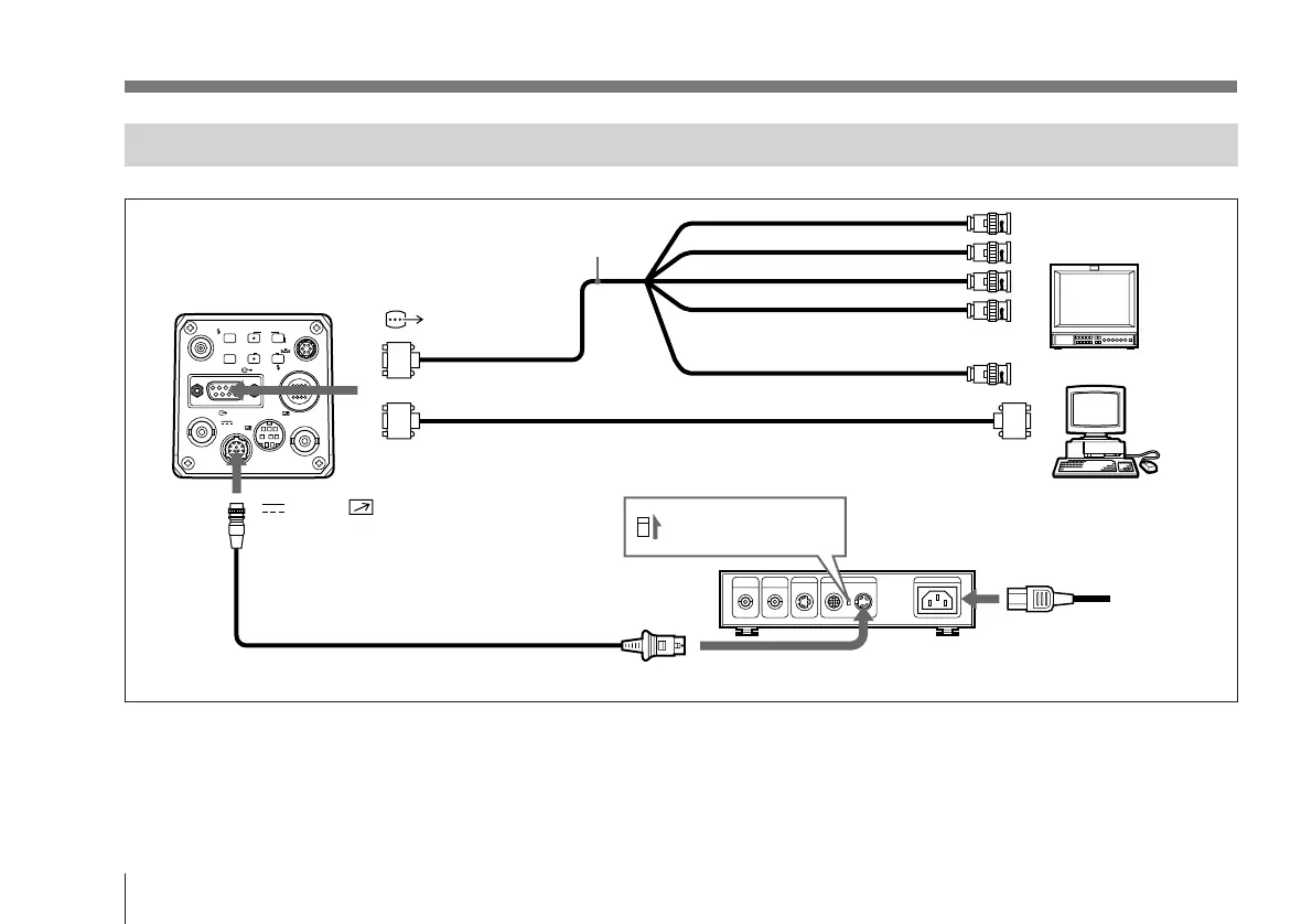
Connecting to Video Equipment With RGB or S-Video Inputs
VIDEO OUT
GEN LOCK
DC IN/
REMOTE
CCU
FLASH
LENS
MENU FUNCTION DATA
UP
WHITE
BARS
DOWN
RGB/SYNC
REMOTE
1
2
R input
G input
B input
Set the MODE selector
to the “1” position.
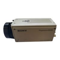
DXC-970MD
RGB/SYNC
or
Camera cable CCXC-9DD (D-
sub 9-pin Nn D-sub 9 pin)
AC IN
CAMERA (4-pin) connector
If a CCMC cable is used, the S-video signal is also
output from the S-video output of the CMA-D2MD.
CCDC-5/10/25/50A/100A cable or
CCMC-12P02/05/10/25 cable
DC IN/ REMOTE
CMA-D2MD
camera adaptor
Computer, image
processor etc.
RGB monitor, image
processor, etc.
Power
cord
Sync input
a)
Composite video (BNC) or
S-video input (4-pin)
b)
RGB/SYNC
b)This setup is for connecting to a composite video (VBS)
connector. To send separated Y/C signals to the S-video
input of video equipment, use a CCMC-9DS camera cable.
For details on switching camera output between VBS
(composite video) and Y/C, see page 97.
a)When using a video monitor without a sync signal input
connector, the camera can be set to output a sync signal
with the G signal (G.SYNC).
For details, see page 96.
Basic System Connection
Camera cable: CCXC-9DB (D-sub 9-pin Nn BNC
connectors), or CCMC-9DS (D-sub 9-pin Nn BNC,
S-video connectors)