77
VIDEO OUT
GEN LOCK
DC IN/
REMOTE
CCU
FLASH
LENS
MENU FUNCTION DATA
UP
WHITE
BARS
DOWN
RGB/SYNC
REMOTE
VIDEO OUT
GEN LOCK
DC IN/
REMOTE
CCU
FLASH
LENS
MENU FUNCTION DATA
UP
WHITE
BARS
DOWN
RGB/SYNC
REMOTE
1
2
1
2
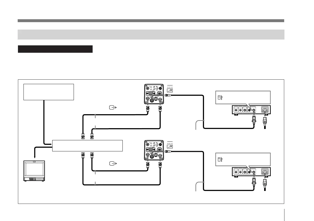
Connections for a Multi-Camera System
• Adjust the subcarrier and horizontal synchronization
phases for all cameras.
For more details, see “Adjusting the Picture Tone in a
Multi-Camera System” on page 104.
CCDC-5/10/25/50A/100A cable
VIDEO IN
GEN LOCK
Set the MODE selector
to the “1” position.
Set the MODE selector
to the “1” position.
CMA-D2MD camera adaptor
CMA-D2MD camera adaptor
AC outlet
Sync (VBS or
BS) output
Sync signal
generator or camera
VBS (BS) OUT
75Ω coaxial cable
75Ω coaxial cable
CCDC-5/10/25/50A/100A cable
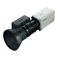
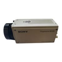
DXC-970MD
Video switcher, etc.
GEN LOCK
DC IN/
REMOTE
DC IN/
REMOTE
Video monitor, VCR, etc.
AC IN
Power
cord
Notes on multi-camera systems
Take the following steps to prevent flicker when switching
between two or more cameras connected to a video switcher:
• Supply the same sync signal to the GEN LOCK
connectors on each camera (see below).
VBS (BS) OUT
VIDEO IN
CAMERA (4-pin)
CAMERA (4-pin)
VIDEO OUT
VIDEO OUT
DXC-970MD