68
VIDEO OUT
GEN LOCK
DC IN/
REMOTE
CCU
FLASH
LENS
MENU FUNCTION DATA
UP
WHITE
BARS
DOWN
RGB/SYNC
REMOTE
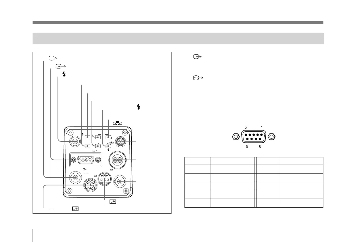
1 VIDEO OUT (output) connector (BNC-type)
Outputs (composite) video signals from the camera module.
2 RGB/SYNC (RGB/sync signal output)
connector (D-sub 9-pin)
Outputs RGB signals and their respective sync signals. Use
a CCXC-9DB/CCXC-9DD/CCMC-9DS cable for the
connections.
Pin assignment
Pin No. Signal Pin No. Signal
1 GND 6 VBS (Y) output
2 GND 7 SYNC/WEN output
3 RED (R-Y) output 8 GND
4 GREEN (Y) output 9 NC (C output)
5 BLUE (B-Y) output
Rear Panel
1 VIDEO OUT connector
2 RGB/SYNC connector
3 FLASH connector
4 BARS button
5 MENU button
6 FUNCTION UP/DOWN buttons
8 DATA UP/
WHITE button
7 DATA DOWN/ button
9 LENS
connector
0 CCU
connector
!¡ GEN LOCK
connector
!™ REMOTE connector
!£ DC IN/ REMOTE connector
Location and Function of Parts and Controls