84
Connector Pin Assignments
Appendix
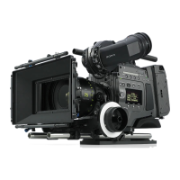
USB
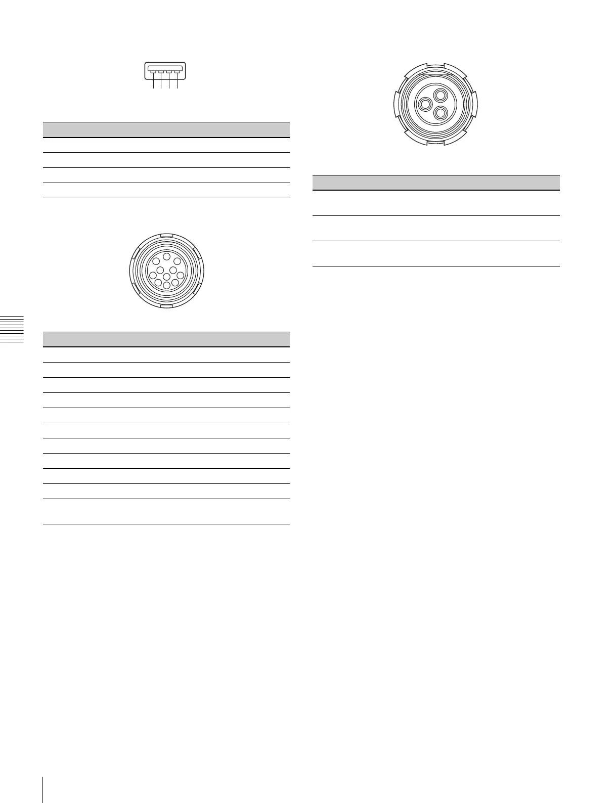
DC OUT 12 V (11-pin female)
DC OUT 24 V (3-pin female)
No. Signal I/O Specifications
1 VBUS OUT 5 V dc, 500 mA (max)
2D- IN/OUT
3D+ IN/OUT
4GND —
No. Signal I/O Specifications
1NC
2NC
3NC
4NC
5NC
6NC
7NC
8NC
9 UNREG_GND —
10 NC
11 UNREG_12
V_OUT
OUT +12 V DC
4 A (MAX)
1234
(External View)
8
9
1
7
6
5
4
3
2
10
11
(External View)
No. Signal I/O Specifications
1 UNREG_GND (24
V)
—
2 UNREG_24
V_OUT
OUT +24 V DC
4 A (MAX)
3 REC trigger IN OPEN or +5 V: Normal
GND: Active
2
1
3
(External View)