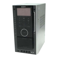
HCD-AZ33D
2
Notes on chip component replacement
• Never reuse a disconnected chip component.
• Notice that the minus side of a tantalum capacitor may be dam-
aged by heat.
Flexible Circuit Board Repairing
• Keep the temperature of soldering iron around 270 °C during
repairing.
• Do not touch the soldering iron on the same conductor of the
circuit board (within 3 times).
• Be careful not to apply force on the conductor when soldering
or unsoldering.
SAFETY-RELATED COMPONET WARNING!
COMPONENTS IDENTIFIED BY MARK 0 OR DOTTED LINE
WITH MARK 0 ON THE SCHEMATIC DIAGRAMS AND IN
THE PARTS LIST ARE CRITICAL TO SAFE OPERATION.
REPLACE THESE COMPONENTS WITH SONY PARTS
WHOSE PART NUMBERS APPEAR AS SHOWN IN THIS
MANUAL OR IN SUPPLEMENTS PUBLISHED BY SONY.
SELF DIAGNOSIS FUNCTION
Self-diagnosis Function
(When letters/numbers appear in the
display)
When the self-diagnosis function
is activated to prevent the system
from malfunctioning, a 5-character
service number (e.g. C 13 50) with a
combination of a letter and 4 digits
appears on the TV screen or the front
panel display. In this case, check the
following table.
First 3
characters of
the service
number
Cause and corrective
action
C 13
Clean the disc with a
C 31
correctly.
Restart the system,
then re-insert the
disc correctly.
EXX
(XX is a
number)
To prevent a
malfunction, the
system has performed
the self-diagnosis
function.
Contactyournearest
Sony dealer or local
authorized Sony
service facility and
give the 5-character
service number.
Example: E 61 10
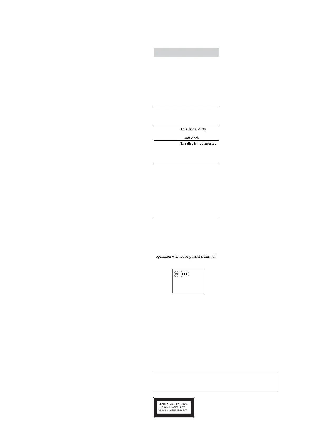
When displaying the version number
on the TV screen
When you turn on the system, the
version number [VER.X.XX] (X is a
number) may appear on the TV screen.
Although this is not a malfunction and
for Sony service use only, normal system
the system, and then turn on the system
again to operate.
This appliance is
classified as a CLASS 1
LASER product. This
marking is located on the
rear exterior.
CAUTION
Use of controls or adjustments or performance of procedures other than
those specifi ed herein may result in hazardous radiation exposure.
Tape deck section
Recording system:
4.track 2.channel, stereo
Tuner section
FM stereo, FM/AM superheterodyne tuner
FM tuner section
Tuning range:
87.5 – 108.0 MHz (50 kHz step)
Antenna:
FM lead antenna
Antenna terminals:
75 Ω unbalanced
Intermediate frequency:
10.7 MHz
AM tuner section
Tuning range:
European and Russian models:
531 – 1,602 kHz (with the interval set at 9 kHz)
Australian model:
531 – 1,710 kHz (with the interval set at 9 kHz)
530 – 1,710 kHz (with the interval set at 10 kHz)
Other models:
531 – 1,602 kHz (with the interval set at 9 kHz)
530 – 1,610 kHz (with the interval set at 10 kHz)
Antenna:
AM loop antenna
Antenna terminals:
External antenna terminal
Intermediate frequency:
450 kHz
General
Power requirements
European model:
AC 230 V, 50/60 Hz
Australian model:
AC 230 – 240 V, 50/60 Hz
Russian and Indian models:
AC 220 – 240 V, 50/60 Hz
Thai model:
AC 220 V, 50/60 Hz
Other models:
AC 120, 220 – 240 V, 50/60 Hz, adjustable with
voltage selector
Power consumption:
65 W (European model: 0.4 W in Power Saving
Mode)
Dimensions (w/h/d) (excl. speakers):
Approx. 190 × 380 × 325 mm
Mass (excl. speakers):
Approx. 6.0 kg
Design and specifi cations are subject to change without
notice.