HCD-AZ33D
26
SECTION 5
MECHANICAL ADJUSTMENTS
SECTION 6
ELECTRICAL ADJUSTMENTS
PRECAUTION
1. Clean the following parts with a denatured-alcohol-moistened
swab :
record/playback head pinch roller
erase head rubber belts
capstan idlers
2. Demagnetize the record/playback head with a head demagne-
tizer.
3. Do not use a magnetized screwdriver for the adjustments.
4. After the adjustments, appiy suitable locking compound to the
parts adjusted.
5. The adjustments should be performed with the rated power
supply voltage unless otherwise noted.
• Torque Measurement
Mode Torque Meter Meter Reading
FWD CQ-102C
3.06 N • m to 6.96 N • m
31 to 71 g • cm
(0.43 – 0.98 oz • inch)
FWD
Back Tension
CQ-102C
0.19 N • m to 0.58 N • m
2 to 6 g • cm
(0.02 – 0.08 oz • inch)
REV CQ-102RC
3.06 N • m to 6.96 N • m
31 to 71 g • cm
(0.43 – 0.98 oz • inch)
REV
Back Tension
CQ-102RC
0.19 N • m to 0.58 N • m
2 to 6 g • cm
(0.02 – 0.08 oz • inch)
FF/REW CQ-201B
6.96 N • m to14.02 N • m
71 to 143 g • cm
(0.98 – 1.99 oz • inch)
FWD Tension CQ-403A
9.80 N • m
100 g or more
(3.53 oz or more)
REV Tension CQ-403R
9.80 N • m
100 g or more
(3.53 oz or more)
1. Demagnetize the record/playback head with a head demagne-
tizer.
2. Do not use a magnetized screwdriver for the adjustments.
3. After the adjustments, apply suitable locking compound to the
parts adjust.
TEST TAPE
Tape Signal Used for
P-4-A063 6.3 kHz, -10 dB Azimuth Adjustment
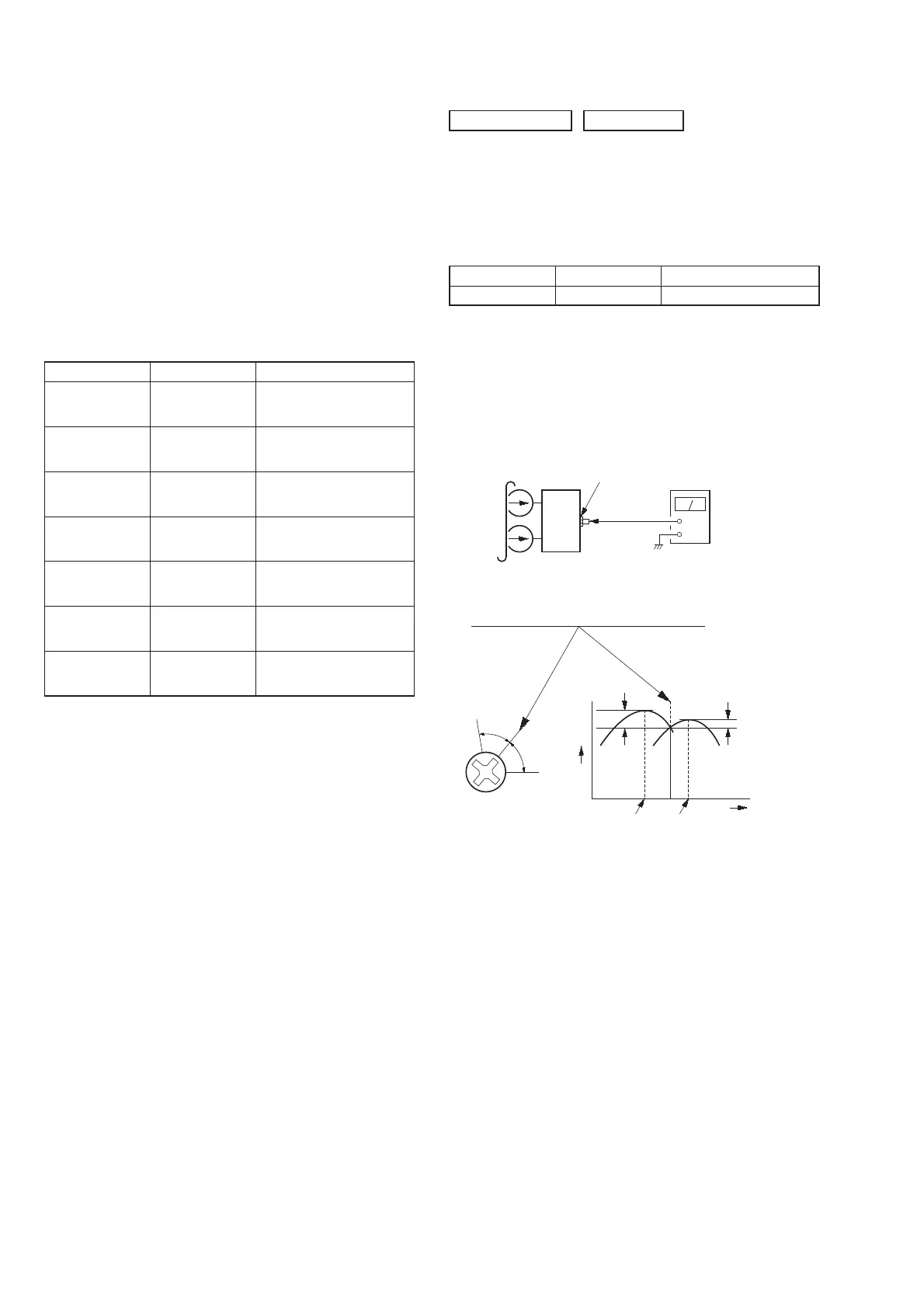
RECORD/PLAYBACK HEAD AZIMUTH ADJUSTMENT
Note: Perform this adjustments for both decks.
Procedure:
1. Mode: Playback
set
MAIN board
VIDEO/SAT OUT
jack (J101)
+
–
level meter
test tape
P-4-A063
(6.3 kHz, –10 dB)
2. Turn the adjustment screw and check output peaks. If the peaks
do not match for L-CH and R-CH, turn the adjustment screw
so that outputs match within 1dB of peak.
Screw
position
L-CH
peak
within
1dB
Output
level
L-CH
peak
R-CH
peak
within
1dB
Screw
position
R-CH
peak
DECK SECTION 0 dB = 0.775V