HCD-AZ33D
27
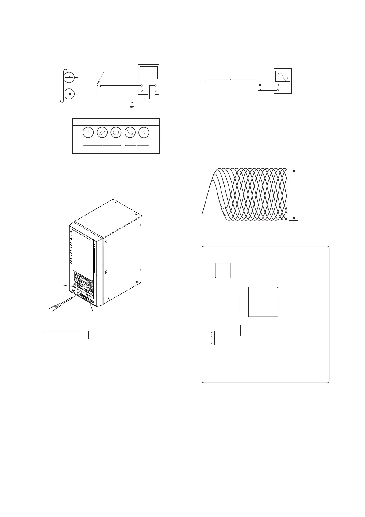
3. Mode: Playback
set
test tape
P-4-A063
(6.3 kHz, –10 dB)
oscilloscope
V
H
waveform of oscilloscope
in phase 45° 90° 135° 180°
good
wrong
MAIN board
VIDEO/SAT OUT
jack (J101)
4. After the adjustments, apply suitable locking compound to the
pats adjusted.
Adjustment Location: Record/Playback/Erase Head
Note: Holder (cassette) of front panel to detach.
reverse
forward
DVD SECTION
TEST DISC LIST
Use the following test disc on electrical adjustments.
YEDS-18 (CD) : PART No. 3-702-101-01
PATD-012 (CD) : PART No. 4-225-203-01
HLX-503 (DVD-SL) (NTSC) : PART No. J-6090-069-A
HLX-504 (DVD-SL) (NTSC) : PART No. J-6090-088-A
HLX-506 (DVD-SL) (PAL) : PART No. J-6090-077-A
HLX-501 (DVD-DL) (NTSC) : PART No. J-6090-071-A
HLX-505 (DVD-DL) (NTSC) : PART No. J-6090-089-A
HLX-507 (DVD-DL) (PAL) : PART No. J-6090-078-A
Note: Do not use excepting test disc for DVD.
ADJUSTMENT AFTER OPTICAL PICK-UP BLOCK RE-
PLACED
After optical pick-up block is replaced, adjustment is necessary. In
this case, perform “EXECUTING IOP MEASUREMENT” (Refer
to page 23 in TEST MODE) next.
RF LEVEL CHECK
+
–
DMB17 board
CN105 pin (RFMON)
CN105 pin (GND)
oscilloscope
(DC range)
Procedure :
1. Connect the oscilloscope to CN105 pin 6 (RFMON) and
CN105 pin 3 (GND) on the DMB17 board.
2. Press the [I/
1
] button to turn the power on.
3. Insert the test disc and touch the [
Y
] sensor to playback.
4. Confi rm that oscilloscope waveform is as shown in the fi gure
below. (eye pattern)
A good eye pattern means that the diamond shape (◊) in the
center of the waveform can be clearly distinguished.
VOLT/DIV: 200 m
TIME/DIV: 500 ns
level:
0.8 ± 0.2 Vp-p (DVD)
0.8 ± 0.2 Vp-p (CD)
Checking Location:
– DMB17 Board (Component Side) –
6
1
CN105
IC104
IC102
IC101
IC201