43
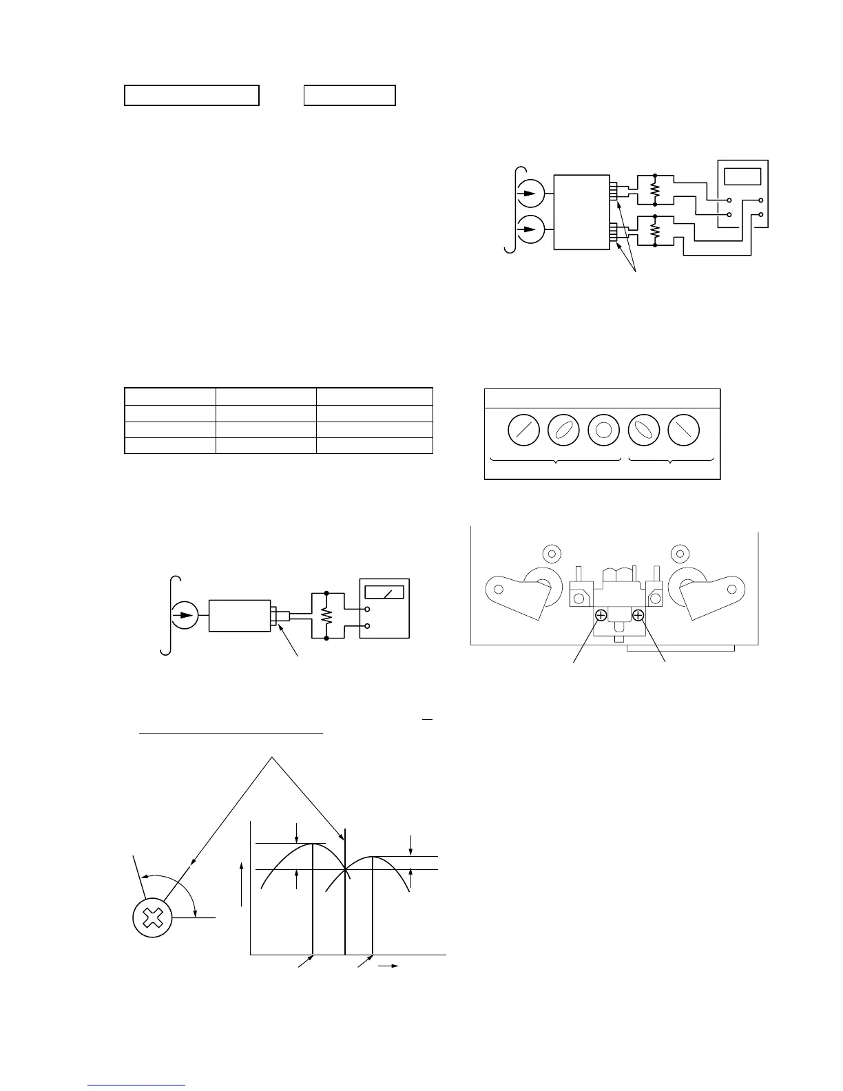
2. Turn the adjustment screw and check output peaks. If the peaks
do not match for L-CH and R-CH, turn the adjustment screw so
that outputs match within 1 dB of peak.
Record/Playback Head Azimuth Adjustment
Procedure:
1. Mode : REV playback
Tape Signal Used for
P-4-A100
WS-48B
P-4-L300
10 kHz, –10 dB
3 kHz, 0 dB
315 Hz, 0 dB
Azimuth Adjustment
Tape Speed Adjustment
Level Adjustment
tast tape
P-4-A100
(10kHz, |10dB)
set
LINE OUT
47kΩ
level meter
L-CH
peak
R-CH
peak
screw
position
output
level
within
1 dB
L-CH
peak
R-CH
peak
screw
position
within 1dB
3. Phase check
Model: REV playback
CASETTE SECTION 0 dB=0.775V
Note: Before starting the adjustment, measure performance of the
machine. Perform adjustment only when the measured
performances do not satisfy the specifications.
1. Demagnetize the record/playback head with a head demagnetizer.
2. Do not use a magnetized screwdriver for the adjustments.
3. After the adjustments, apply suitable locking compound to the
parts adjusted.
4. The adjustments should be performed with the rated power supply
voltage unless otherwise noted.
completed before performing recording circuit adjustment.)
5. The adjustments should be performed in the order given in this
service manual. (As a general rule, playback circuit adjustment
should be completed before performing recording circuit
adjustment.)
6. The adjustments should be performed for both L-CH and R-CH.
7. Switches and controls should be set as follows unless otherwise
specified.
4. Perform steps 1 to 3 in the FWD playback mode.
5. Confirm that phase error between L-ch and R-ch is in the range
of same phase to 90 degrees.
6. After the adjustments, apply suitable locking compound to the
parts adjusted.
Adjustment Location:
Waveform of oscilloscope
in phase 45°
90°
135°
180°
good
wrong
Adjustment screw
(FWD mode)
Adjustmednt screw
(REV mode)