28
HCD-M90
Note: Confirm each contents of this section first of all. If the results are
not satisfied, do the adjustment.
1. The adjustments should be performed with the rated power supply
voltage unless otherwise noted.
2. The adjustments should be performed in the order given in this service
manual.
3. The adjustments should be performed for both L-CH and R-CH.
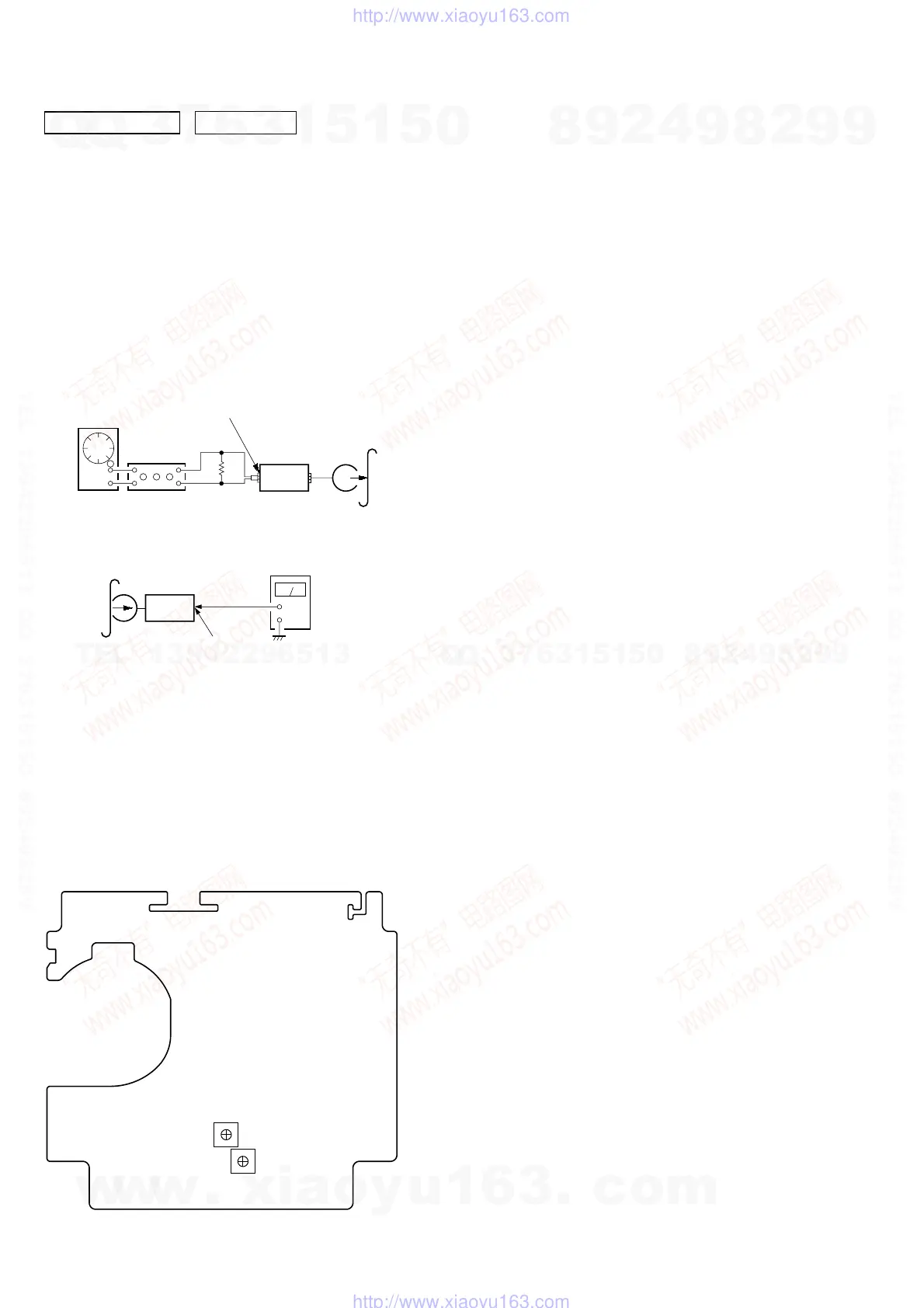
REC BIAS ADJUSTMENT
Procedure:
1. Mode: REC
FUNCTION: MD
2. Mode: Playback
3. Confirm playback the signal recorded in step 1 become speci-
fied values as follows.
If these values are out of specification values, adjust the RV101
(L-CH) and RV201 (R-CH) on the TC board to repeat steps
1and 2.
Specified values: Playback output of 315 Hz to playback
output of 10 kHz: ± 0.5 dB
Adjustment Location: TC board
attenuator
set
MAIN board
AUDIO IN (MD/VIDEO) jack (SJ302)
L-CH, R-CH
1) 315 Hz
2) 10 kHz
50 mV (– 23.8 dB)
600
Ω
blank tape
CN-123
AF OSC
+
–
set
recorded
portion
MAIN board
SPEAKER terminals (SJ301
L-CH, R-CH
level meter
0 dB=0.775 V
DECK SECTION
RV101 (L)
RV201 (R)
REC Bias
Adjustment
– TC BOARD (Component Side) –
w
w
w
.
x
i
a
o
y
u
1
6
3
.
c
o
m
Q
Q
3
7
6
3
1
5
1
5
0
9
9
2
8
9
4
2
9
8
T
E
L
1
3
9
4
2
2
9
6
5
1
3
9
9
2
8
9
4
2
9
8
0
5
1
5
1
3
6
7
3
Q
Q
TEL 13942296513 QQ 376315150 892498299
TEL 13942296513 QQ 376315150 892498299
http://www.xiaoyu163.com
http://www.xiaoyu163.com