51
HCD-XG60/XG500
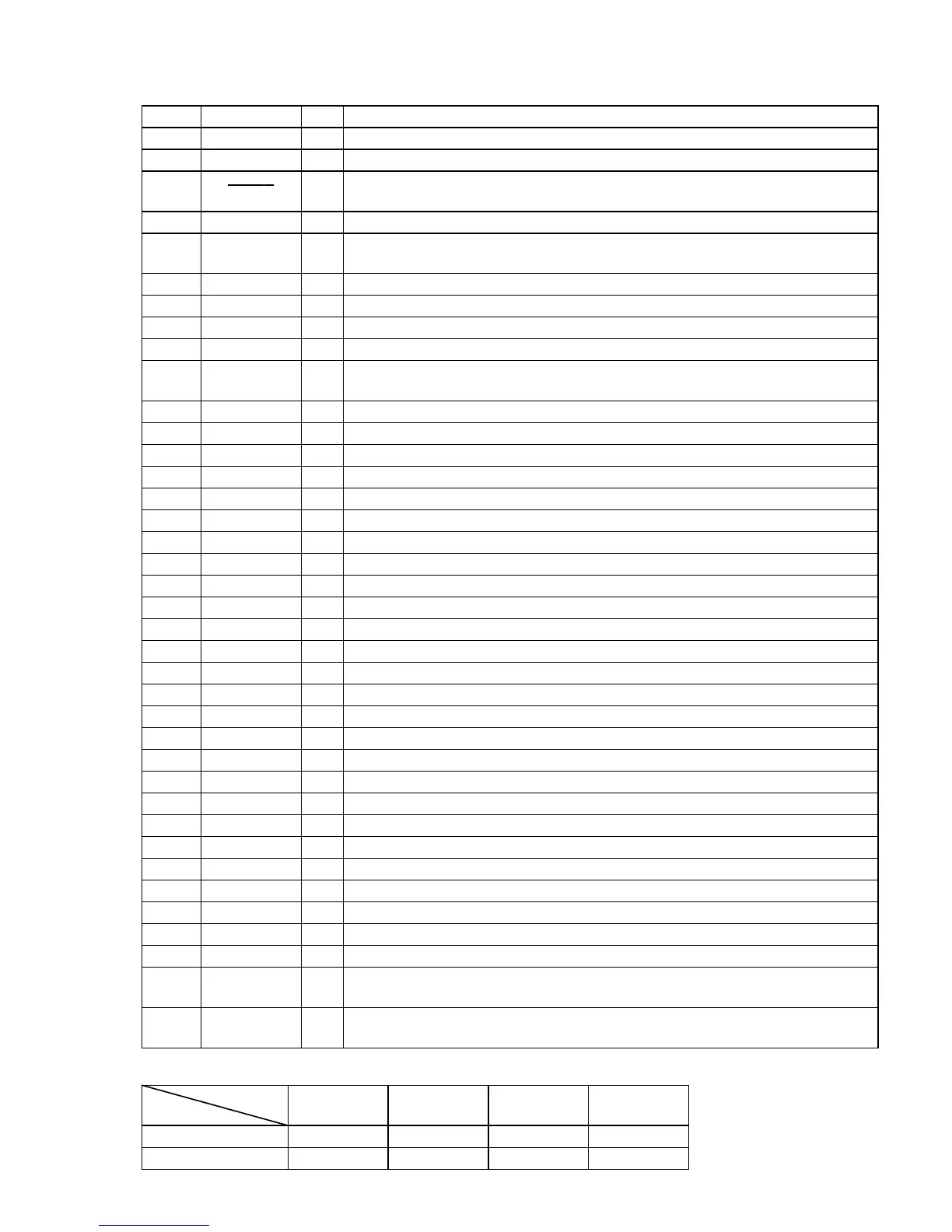
Pin No. Pin Name I/O Description
39 CLOCK-OUT O
Not used (open)
40, 41 NO-USE O
Not used (open)
42 FL OFF O
Filament on/off selection signal output for the fluorescent indicator tube (FL601)
“L”: filament off, “H”: filament on Not used in this set
43 STBY RELAY O
Main power on/off control signal output “L”: standby mode, “H”: power on
44 BASS FREQ O
Sync bass frequency normal/high selection signal output terminal
“L”: sync bass off (normal), “H”: sync bass high Not used (open)
45 FUNC SEL1 O
Function selection signal output to the BA7615N (IC191)
46 FUNC SEL0 O
Function selection signal output to the BA7615N (IC191)
47 493-DATA O
Serial data output to the M62493FP (IC101)
48 493-CLK O
Serial data transfer clock signal output to the M62493FP (IC101)
49 ST-MUTE O
Tuner muting on/off control signal output to the FM/AM tuner unit
“L”: muting off, “H”: muting on
50 STEREO I
FM stereo detection signal input from the FM/AM tuner unit “L”: stereo
51 TUNED I
Tuning detection signal input from the FM/AM tuner unit “L”: tuned
52 ST-CE O
PLL chip enable signal output to the FM/AM tuner unit
53 ST-DOUT O
PLL serial data output to the FM/AM tuner unit
54 ST-DIN I
PLL serial data input from the FM/AM tuner unit
55 ST-CLK O
PLL serial data transfer clock signal output to the FM/AM tuner unit
56
SENS I Internal status detection monitor input from the CXD2587Q (IC101)
57 HOLD
O Laser power control signal output to the CXA2568M (IC103)
58 XLT
O Serial data latch pulse output to the CXD2587Q (IC101)
59 XRST
O Reset signal output to the CXD2587Q (IC101) and BA5974FP (IC102) “L”: reset
60 DISC-SENS I
Disc status detection signal input terminal Not used (fixed at “L”)
61 T-SENS I
Disc table status detection signal input from the disc table sensor (IC202)
62 VDD —
Power supply terminal (+5V)
63 TBL-L O
Motor drive signal output to the table motor driver (IC201) “L” active *1
64 VSS —
Ground terminal
65 TBL-R O
Motor drive signal output to the table motor driver (IC201) “L” active *1
66 LOAD-OUT O
Loading motor drive signal output terminal Not used (open)
67 LOAD-IN O
Loading motor drive signal output terminal Not used (open)
68 ENC3/UP-SW I
Detection signal input from the up switch (S201)
69 ENC2/DISC-LED O
LED drive signal output of the DISC No. indicator (D201) “H”: LED on
70 ENC1 I
Disc tray address detection signal input terminal Not used (fixed at “L”)
71 OUT-OPEN I
Disc tray open/close detection signal input terminal Not used (fixed at “L”)
72 B-TRG O
Deck-B side trigger plunger drive signal output “H”: plunger on
73 A-TRG O
Deck-A side trigger plunger drive signal output “H”: plunger on
74 CAPM-CNT2 O
Capstan motor (M1) drive signal output “L”: reverse direction, “H”: forward direction
75 CAPM-CNT1 O
Capstan motor drive signal output terminal Not used (open)
76 CAP-M-H/L O
High/normal speed selection signal output of the capstan motor (M1)
“L”: normal speed, “H”: high speed
77 AMS-IN I
Whether a music is present or not from HA12215F (IC301) is detected at automatic music sensor
“L”: music is present, “H”: music is not present
*1 Table motor (M201) control
Stop
Counter-
clockwise
Clockwise Brake
TBL-L (pin yd)
“H”“L”“H”
“L”
TBL-R (pin yg)
“H”“H”“L”
“L”
Terminal
Mod

 Loading...