17
STR-DA5000ES
OSD ADJUSTMENT
Connection
1. Short the TP3501 pin 4 on the VIDEO board to the GND.
2. Connect a frequency counter to the TP3501 pin 2 on the VIDEO
board.
3. Press the I/1 button to turn on the main power.
4. Press the [ON SCREEN] button on the remote commander.
5. Turn the [MAIN MENU] jog to display “CUSTOMIZE”.
6. Turn the [MENU] jog to display “COLOR SYSTEM”.
7. Turn the [--/+] jog to display “NTSC”.
8. Adjust the CT3502 (US, Canadian and Taiwan models) or
CT3503 (except US, Canadian and Taiwan models) so that the
frequency counter reading is 3.579545±0.05 MHz.
9. Turn the [MENU] jog to display “COLOR SYSTEM”.
10. Turn the [--/+] jog to display “PAL”.
11. Press the [ON SCREEN] button on the remote commander.
12. Adjust the CT3504 so that the frequency counter reading is
4.433618±0.05 MHz.
13. Press the I/1 button to turn off the main power.
14. Connect a frequency counter to the CN3501 pin 1 on the
VIDEO board.
15. Press the I/1 button to turn on the main power.
16. Press the [ON SCREEN] button on the remote commander.
17. Adjust the CT3501 so that the frequency counter reading is
7.20±0.01 MHz.
Note: The steps 5 to 7 and 9 to 12 should be performed to the models
except for the US, Canadian and Taiwan.
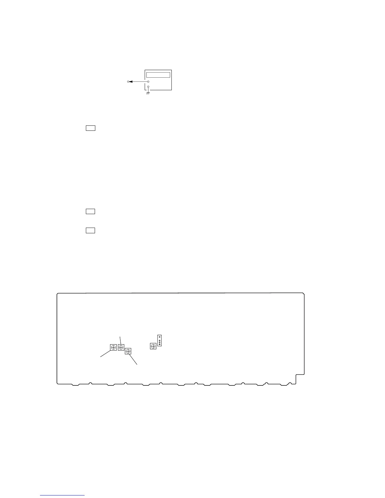
Adjustment and Connection Location:
VIDEO board
TP3501 pin
1
or pin
2
+
–
frequency counter
– VIDEO BOARD (Component Side) –
CT3504
(AEP, Chinese models)
CT3503
(AEP, Chinese models)
CT3501
TP3501
1
4
CT3502
(except AEP, Chinese models)