8
Technical data are subject to change without notice.
ISO 9001 certified. © Copyright SPM 1996-9. 71416.B
SPM Instrument AB • Box 4 • S-645 21 Strängnäs • Sweden
Tel +46 152 22500 • Fax +46 152 15075 • info@spminstrument.se • www.spminstrument.se
Shock Pulse Transducers and Accessories
A basic requirement for condition monitoring is ac-
cess to suitable measuring points. Over the last 20
years, SPM has developed a large range of accesso-
ries and installation components which enable the
customer to reach bearings in almost any application.
The A2011 offers three alternative ways of measuring
shock pulses:
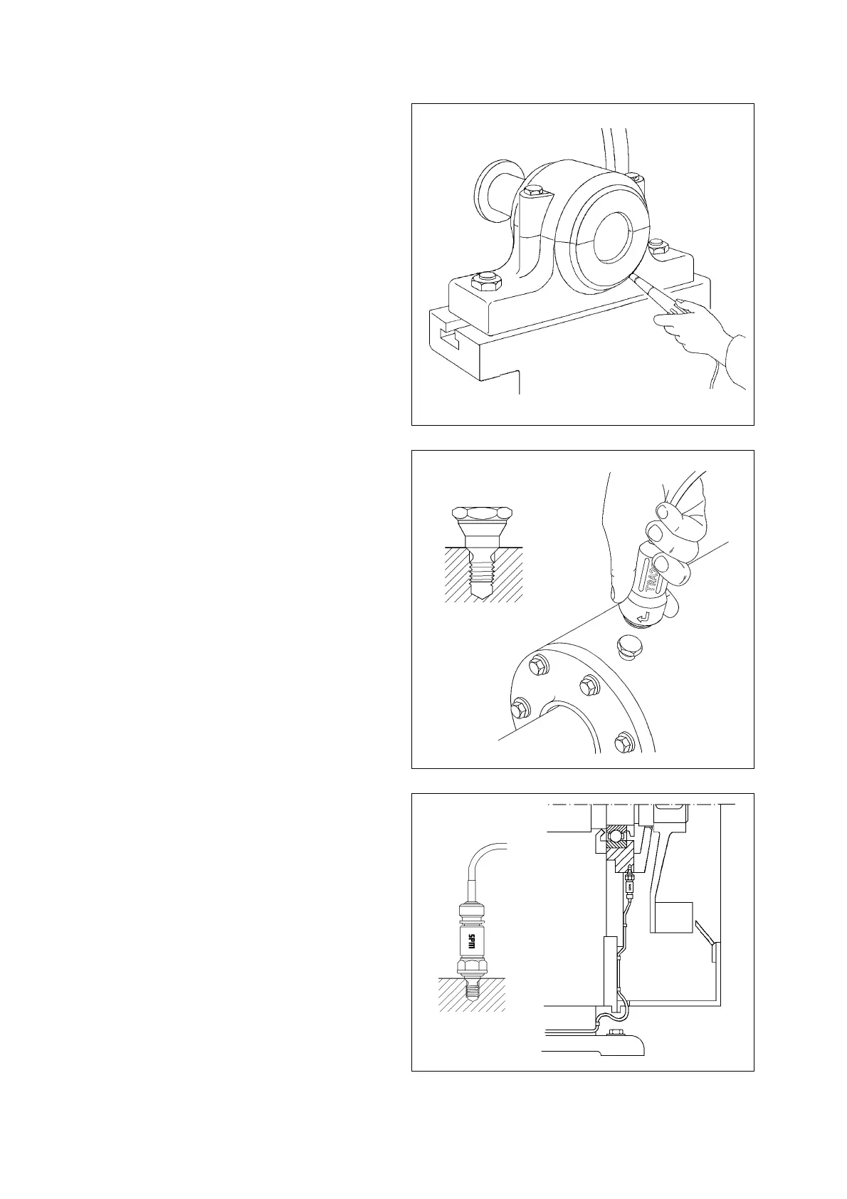
• a hand-held probe is pressed against the bearing
housing.
• an adapter is permanently installed on the bea-
ring housing. Readings are taken by attaching a
transducer with quick connector to the adapter.
• a shock pulse transducer is permanently installed
on the bearing housing and via coaxial cable
connected to a measuring terminal. Readings are
taken by connecting the A2011 to the terminal.
The hand-held probe is used for spot checks, for
locating the best measuring points for systematic moni-
toring, and for tracing other shock pulse sources on
the machine, for example cavitation or rubbing and
scraping machine parts.
For systematic shock pulse monitoring, SPM recom-
mends the use of permanently installed adapters (fig-
ure 7). Adapters are solid steel bolts, installed in
threaded, countersunk mounting holes. The transducer
is connected with a quick twist, leaving the operators
hands free for the instrument.
Adapters make clearly defined measuring points and
permit more accurate readings with less spread.
An alternative is the SPM transducer TRA-20 which
snaps on to a measuring stud. Studs are installed in
threaded holes. Studs as well as adapters are avail-
able in glue-on versions for thin-walled bearing
housings.
Permanently installed transducers (fig. 8) are primarily
used for bearings which cannot be reached in any
other way during normal machine operation. The nor-
mal cable length is up to 4 m between bearing and
measuring terminal. Transducer matching units allow
cable lengths of up to 100 m.
Fig. 6
Adapter
Fig. 7
Fig. 8
Transducer