22
Technical data are subject to change without notice.
ISO 9001 certified. © Copyright SPM 1996-9. 71416.B
SPM Instrument AB • Box 4 • S-645 21 Strängnäs • Sweden
Tel +46 152 22500 • Fax +46 152 15075 • info@spminstrument.se • www.spminstrument.se
Instrument On / Off
The A2011 is switched on by pressing any key.
Power down is automatic when no key is pressed
within the time entered under SETUP, OFF. If the
instrument fails to power down after that time, press
the unmarked master reset key (9).
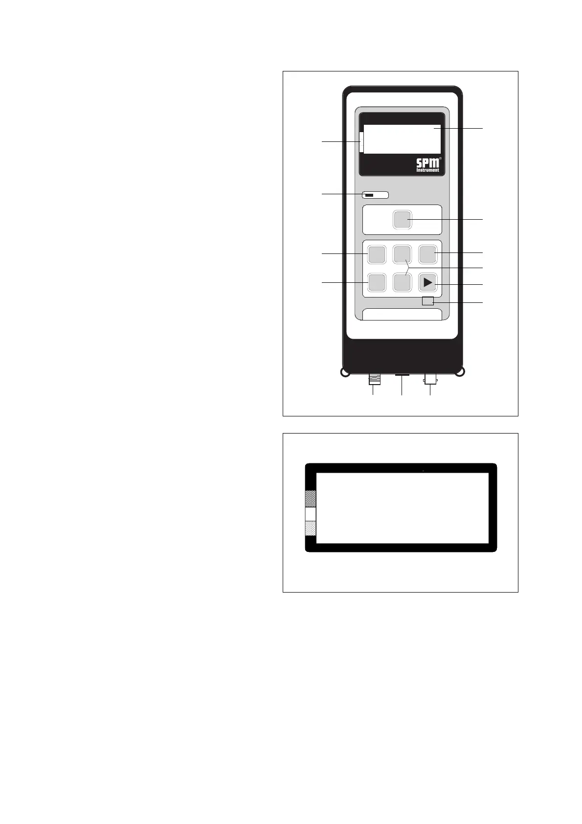
Fig. 1
COMMUNICATION
TIME
VERSION
SETUP
Select menu
Fig. 2
The two measuring modes are ”Data logging” (meas-
uring points and input data downloaded from the PC)
and ”Manual” (data input via instrument keys).
1 Display
2 Condition scale
3 Peak indicator
4 Measuring key (M)
5 Set key (SET)
6 Enter key (ENT)
7 Arrow keys (UP / DOWN)
8 Arrow keys (RIGHT / LEFT)
9 Master reset key (unmarked)
10 Connector for shock pulse transducers (SPM)
11 Connector for tachometer probe, earphone,
and PC (EXT)
12 Connector for vibration transducer (VIB).
Transducers and Probes
The TNC connector SPM (10) is used for shock pulse
transducers: hand-held probe, transducer with quick
connector, or a measuring cable connecting via a
measuring terminal to an installed shock pulse trans-
ducer.
The BNC connector VIB (12) is used for the vibration
transducer.
SPM and VIB transducer may be connected simulta-
neously in all modes.
The connector EXT (11) receives the cable CAB-10,
used to connect the tachometer probe, the earphone,
and the PC (via communication module 13603).
In Manual mode, connecting the tachometer probe or
the earphone activates the respective measuring func-
tion. To exit, the cable has to be disconnected.
Instrument Setup
On a new instrument, you have to set:
• the unit for vibration readings, mm/s or inch/s
• the display language
• the switch-off time
• the instrument clock,
using the Select menu (figure 2) and following the
instruction on page 6.
General Functions
▼▼
EXT VIB
M
▲
ENT
▲
▼
SET
SPM
▼
PEAK
DATA LOGGER
BEARING TEST
CODE C ACC 3
LUB — LR 28
COND 28 HR 20
➞
Shock Pulse Analyzer A2011
7
1
4
6
8
9
3
5
8
2
10 11 12