16
Technical data are subject to change without notice.
ISO 9001 certified. © Copyright SPM 1996-9. 71416.B
SPM Instrument AB • Box 4 • S-645 21 Strängnäs • Sweden
Tel +46 152 22500 • Fax +46 152 15075 • info@spminstrument.se • www.spminstrument.se
Taking Shock Pulse Readings
In the Data logger mode, the A2011 will display the
measuring points one by one. A measurement is initi-
ated by pressing ENT (last reading is displayed).
For measurements with manual data input, move to
the BEARING TEST menu with RIGHT/LEFT. Press
SET to change NORM, TYPE, COMP, and Acc, then
press ENT.
After connecting the transducer to the measuring
point, press the M key . While the instrument goes
through the set number of measuring cycles, the peak
indicator blinks and the bearing data are on the screen.
The figure behind Acc shows the number of com-
pleted cycles. The transducer type used is displayed
in the bottom right hand corner of the screen (fig. 25).
After completing the measurement, the A2011 dis-
plays LR and HR together with CODE, LUB, and COND.
An arrow points at the condition scale, green field for
CODE A, yellow for B and C, red for D.
In the Data logger mode, the reading can now be
saved with ENT. Alternatively one can take another
reading by pressing the M key again. Up to 5 readings
can be stored in a temporary memory. They are num-
bered and can be recalled with RIGHT/LEFT. Pressing
ENT stores the displayed reading, deletes the others,
and brings up the next measuring point.
In the Manual mode, the readings are not stored. A
new reading with the same basic data can be started
with M. To change input data, press ENT, then SET.
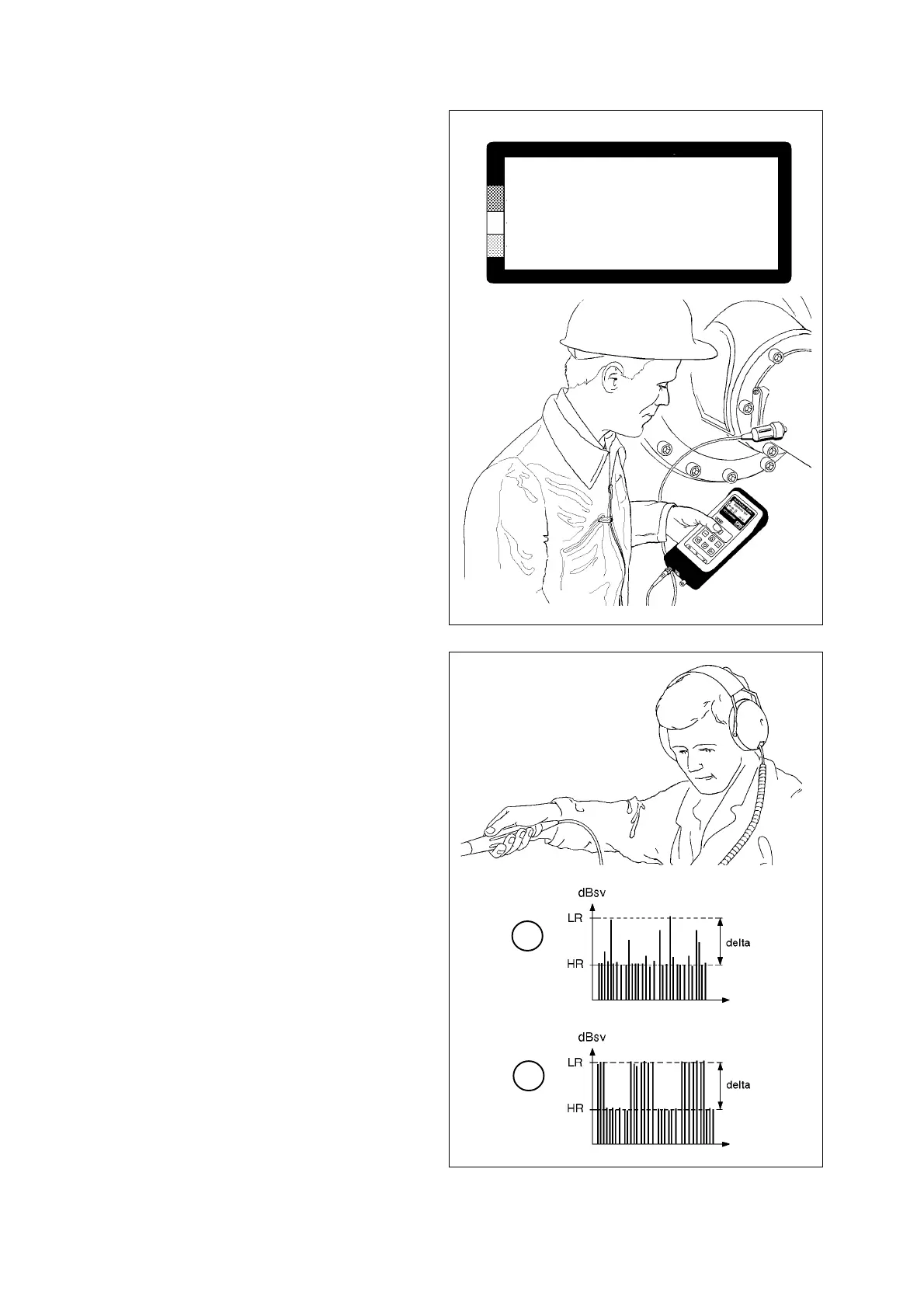
The Earphone Mode
The earphone can be used in Bearing test mode to
listen to the rhythm of the shock pulses and to deter-
mine their probable origin and cause.
The transducer has to be connected to the measuring
point while the earphone is used. UP/DOWN controls
the measuring threshold. The peak indicator blinks if
there are shock pulses above the set level.
Shock pulse sources other than the bearings can nor-
mally be identified by their characteristic sound pat-
tern. Single shock pulses are heard as single sound
pulses, while the shock pulses at the HR level are
heard as a continuous tone. Figure 26 shows two
typical patterns:
A Damaged bearing - strong, irregular, single peaks
well above the HR level.
B Scraping or rubbing machine parts - a shower of
peaks at regular intervals.
Fig. 26
A
B
MEASURING
NORM 32 Acc 0 / 3
TYPE 1
COMP 0 TRA
Fig. 25