7
Technical data are subject to change without notice.
ISO 9001 certified. © Copyright SPM 1996-9. 71416.B
SPM Instrument AB • Box 4 • S-645 21 Strängnäs • Sweden
Tel +46 152 22500 • Fax +46 152 15075 • info@spminstrument.se • www.spminstrument.se
▼▼
EXT VIB
M
▲
ENT
▲
▼
SET
SPM
▼
PEAK
DATA LOGGER
BEARING TEST
CODE C ACC 3
LUB — LR 28
COND 28 HR 20
➞
Shock Pulse Analyzer A2011
SPM
VIB
rpm
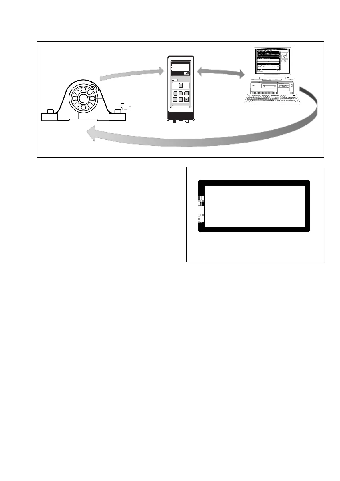
Data Logging with A2011
The simplest and most effective way of using the
A2011 is as a data logger, in combination with the
SPM software CONDMASTER.
The CONDMASTER program is used to
• set up measuring points and store all necessary
input data (NORM and TYPE numbers for bearing
monitoring, machine class for vibration monitor-
ing).
• create measuring rounds and/or work orders,
containing a number of measuring points which
are to be monitored at predetermined intervals
and in a fixed order.
The hierarchy is measuring point - round - work order,
which means that a work order can contain several
rounds and also individual measuring points. For both
rounds and work orders, the user defines a measuring
interval in days. The PC will display the date when the
work is to be carried out, and set a new date when the
measuring results are reported back to the PC.
Downloading Measuring Point Data
Measuring point data are transferred to the A2011 as
follows:
• On the PC, select a round/work order for trans-
fer.
• Connect the A2011 to the PC via the communica-
tion unit.
• Select COMMUNICATION on the A2011 Select
menu, press ENT.
The A2011 has a 32 kb memory and can store at least
257 measuring points. The number is normally greater:
it depends on the length of measuring point number
and name as well as on the number of measuring
techniques used.
A400.001
Raw water pump No. 6
Motor N
SPM 0 0 1
Measuring point data
Fig. 5
Fig. 4
Measuring Point Display
The A2011 will display the measuring points in the
preprogrammed order, showing
• Measuring point number (for very long numbers,
it displays the last 16 characters).
• Measuring point name (on two lines).
• Measuring technique (in the sequence rpm – SPM
– VIB if several are used).
• Running number in the round or work order.
Pressing ENT will display the results of the last read-
ing. To take the new reading, connect the appropri-
ate transducer and press the M key, as described on
the following pages.
One can measure in any order by selecting points
with the UP/DOWN keys. Readings can be repeated -
the last reading stored with ENT will be transferred to
the PC when the measuring results are reported back.
For details, see page 23 to 26.
Route
Input data
Readings