30
Technical data are subject to change without notice.
ISO 9001 certified. © Copyright SPM 1996-9. 71416.B
SPM Instrument AB • Box 4 • S-645 21 Strängnäs • Sweden
Tel +46 152 22500 • Fax +46 152 15075 • info@spminstrument.se • www.spminstrument.se
BEARING TEST
CODE B Acc 3 / 3
LUB 0 LR 31
COND 28 HR 24
Taking Shock Pulse Readings
Connect a shock pulse transducer to the A2011. In
Manual mode, select the Bearing test menu, showing
the results from the last reading (fig. 12). The basic
bearing data last set are shown when the SET key is
pressed (fig. 11).
• Check that the bearing is rotating.
• Press SET and check/change NORM, TYPE,
COMP and Acc. Press ENT.
• Connect the transducer to the measuring point.
• Press the M key.
In Data logging mode, you do not change input data,
and you store the reading with ENT.
A measuring cycle takes approximately 10 seconds.
During measurement, the peak indicator blinks and
the basic bearing data are on the screen. A message
in the lower right hand corner shows which trans-
ducer is being used:
TMU - an installed shock pulse transducer with
TMU (transducer matching unit)
PROBE - the hand-held probe
TRA - a transducer with quick connector or a
permanently installed transducer
without TMU.
Results of a Normalized Reading
The A2011 will accept the reading
• if the NORM No. is min. 10 (min. 18 for the probe
transducer).
• if signal strength and shock pulse pattern are
within the range which is possible for a bearing
with the preset basic data.
The result of a normalized reading is shown in figure
12. It consist of:
CODE A = good condition
B = poor lubrication condition
C = poor surface condition
D = bearing damage
LUB Lubrication number for oil film condition
COND Condition number for surface condition
LR / HR Measured shock values.
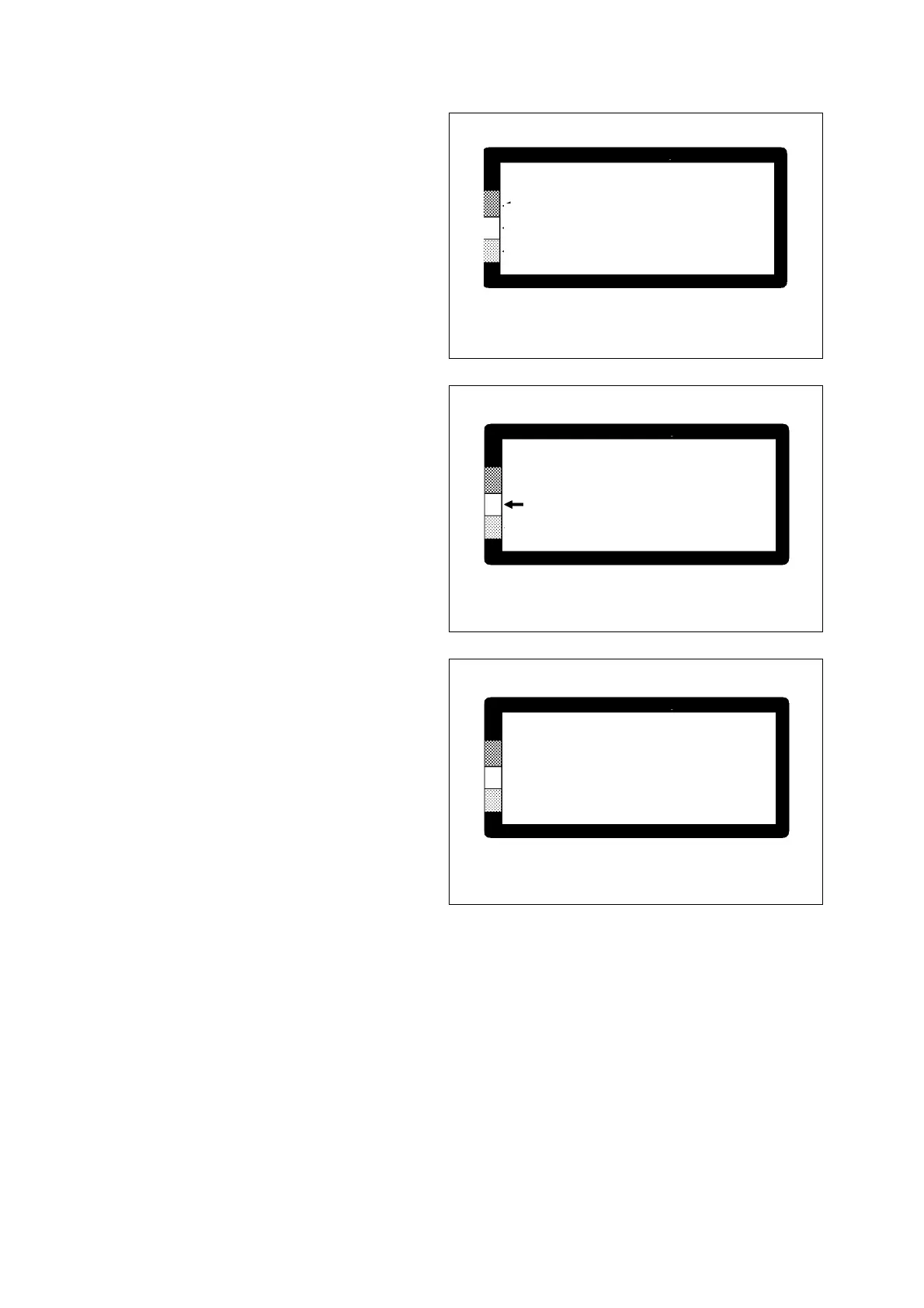
An arrow points at one of the fields on the coloured
scale:
green – good condition (CODE A
)
yellow – caution (CODE B or C)
red – bad condition (CODE D).
MEASURING
NORM 28 Acc 2/3
TYPE 5
COMP 0 TRA
Menu during shock pulse reading
Fig. 11
Result of a normalized reading
Fig. 12
Result of an unnormalized reading
Fig. 13
Unnormalized Readings
When the NORM No. is set to 0, the A2011 will
display LR and HR only (fig. 13). The condition codes
and the arrow are not shown.
Note that LR / HR values are always independent of
the NORM No. The measuring unit is dBsv (decibel
shock value), and the range is from -19 dBsv to +99
dBsv.
BEARING TEST
NORM 0 Acc 3 / 3
LR 24
HR 20