5
Technical data are subject to change without notice.
ISO 9001 certified. © Copyright SPM 1996-9. 71416.B
SPM Instrument AB • Box 4 • S-645 21 Strängnäs • Sweden
Tel +46 152 22500 • Fax +46 152 15075 • info@spminstrument.se • www.spminstrument.se
▼▼
EXT VIB
M
▲
ENT
▲
▼
SET
SPM
▼
PEAK
DATA LOGGER
BEARING TEST
CODE C ACC 3
LUB — LR 28
COND 28 HR 20
➞
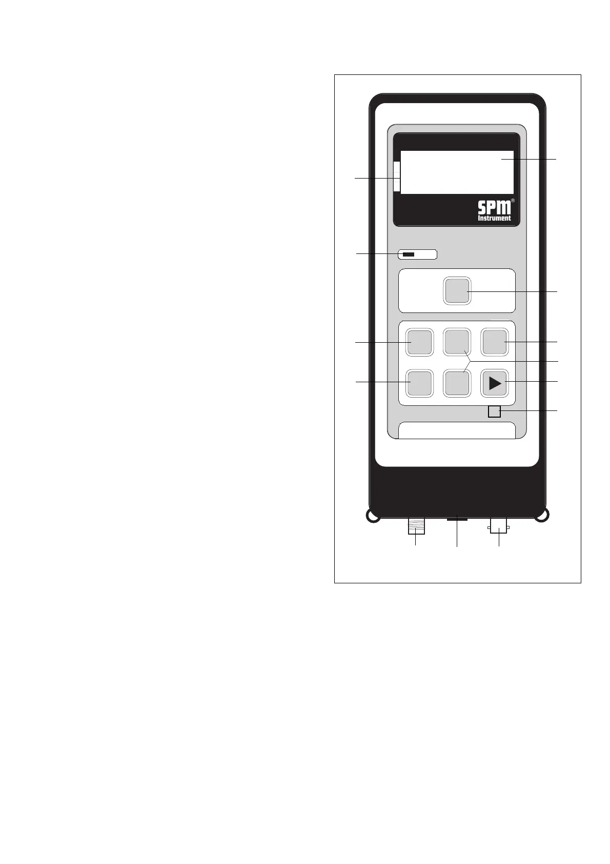
Shock Pulse Analyzer A2011
The A2011 has three inputs, each with a different
connector type, and specialized circuits for all three
measuring functions. Press any key to switch on the
instrument. Switch off is automatic after a preset
number of seconds.
1 LCD Display
On four lines, the display shows menus, selected mea-
suring mode, input data, and measuring results.
2 Condition Scale
An arrow pointing at the green, yellow, or red field of
the condition scale provides an instant evaluation of
the measured shock pulse or vibration level:
green = good condition
yellow = reduced condition
red = bad condition.
3 Peak Indicator
In the earphone mode, a blinking light shows the
existence of shock pulse peaks above the displayed
shock level.
4 Measuring Key
The M key starts the measurement. For continuous
vibration measurement, the key is held down.
5 Set Key
Used to select input data to be changed with the
arrow keys, and to set comments in data logger mode.
6 Enter Key
Stores input data and readings. Selects point and
technique for measurement in data logger mode.
7 Arrow Keys, Up - Down
Used to change entries in the data fields.
8 Arrow Keys, Right - Left
Used to select particular digit to change in a data
entry field. Used to move between the four main
screens.
9 Reset Key
Unmarked key for master reset.
10 Input for Shock Pulse Transducer
A threaded connector receiving the coaxial cable from
a hand-held probe, a transducer with quick connec-
tor, or a measuring terminal.
Instrument Keys and Functions
10
11
12
3
4
6
8
5
9
2
1
8
7
11 Input for Earphone, Tachometer, PC
Connecting the earphone or the tachometer probe
will switch the A2011 to the respective measuring
mode.
This input is also used to connect the A2011 to the PC
for data transfer via communication module SPM
13603.
12 Input for Vibration Transducer
A bayonet connector receiving the coaxial cable from
the vibration transducer.
Fig. 2