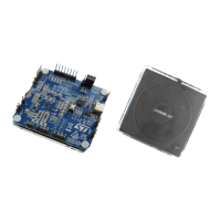
The STEVAL-WLC38RX evaluation board is a versatile tool designed for wireless power receiver applications, enabling users to quickly develop 5W Qi Baseline Power Profile (BPP) and 15W Qi Extended Power Profile (EPP) compatible wireless charging receiver projects. At its core, the board utilizes the STWLC38 wireless power receiver chip, capable of managing up to 15 W of power in accordance with the Wireless Power Consortium's EPP standard. This integrated circuit requires minimal external components, offering high design flexibility.
Function Description
The STEVAL-WLC38RX board facilitates wireless power reception and management. It supports both DC (standalone) mode and AC (wireless power transfer) mode. In DC mode, the receiver is powered by an external DC supply or USB, primarily used for patch and configuration loading. AC mode, conversely, involves powering the receiver from a wireless power transmitter, with a stable power transfer indicated by a continuously lit D7 LED.
The board incorporates several safety mechanisms to ensure reliable operation, including overtemperature (OVTP), overcurrent (OCP), overvoltage (OVP), and foreign object detection (FOD) protections. These protections are crucial for preventing damage to the device and ensuring user safety.
A key feature is the on-board USB-to-I²C converter, which allows users to monitor and control the STWLC38 chip via a PC using the STSW-WPSTUDIO graphical user interface (GUI). This GUI provides real-time access to internal ADC channels, enabling monitoring of voltages, currents, and temperatures. It also facilitates configuration of various parameters, including LDO output voltage, protection thresholds, and FOD tuning.
The STWLC38 supports bidirectional communication. It uses Amplitude Shift Keying (ASK) for the receiver to communicate with the transmitter, modulating the power drawn from the signal to convey information like required power levels (CEP), received power (RPP), signal strength (SS), and charge status (CSP). Frequency Shift Keying (FSK) is used by the transmitter to communicate with the receiver, modulating the power signal's frequency.
Important Technical Specifications
- Qi Compatibility: Qi 1.3 BPP and EPP protocol.
- Rx Application PCB Area: 24 mm x 34 mm.
- Rx Coil Specifications:
- Inductance: 8 µH, DCR 190 mΩ, ACR 225 mΩ.
- Dimensions: 57 mm x 57 mm x 0.42 mm (LD81FP008-1H).
- Output Voltage (Vout, continuous operation): 5 V Baseline Power Profile / 9 V Extended Power Profile.
- Output Current (lout, Load): Recommended current load range is 0.1 - 1 A.
- Host MCU: STM32 (used as a reference; I²C driver can be ported to other MCU families).
- USB-to-I²C Converter: Embedded in the evaluation board.
- Efficiency: 77.6% (5 W operation) with STEVAL-WBC86TX; 81% (peak efficiency) with STEVAL-WBC86TX at 3 W.
- Applicable Charging Gap (z-distance): 3 - 13 mm (5 W output) with STEVAL-WBC86TX transmitter; maximum 16 mm for stable communication without output enabled.
- Misalignment (x-y offset from center): 12 mm for 5 W output; 18 mm for stable communication without output enabled.
- Protections:
- OVP: Ping OVP (POVP), Soft OVP (SOVP), Hard OVP (HOVP), Firmware OVP. Thresholds are configurable.
- UVLO: Input Voltage Loop (IVL), RX UVLO.
- OCP: Hardware OCP, Firmware OCP. Thresholds are configurable.
- OVTP: Hardware Thermal Shutdown (TSHUT), Firmware OVTP, NTC OVTP. Thresholds are configurable.
- LDO Regulators: Two internal LDOs (2.5 V and 1.1 V) for analog and digital parts, respectively.
- Memory: 32kB RRAM, 64kB ROM, 16kB RAM.
Usage Features
- Quick Start: The board allows for rapid prototyping of wireless charging receiver projects.
- GUI Control: The STSW-WPSTUDIO GUI provides comprehensive control and monitoring capabilities, including real-time ADC channel data, register configuration, and patch/firmware updates.
- Flexible Configuration: Users can customize various parameters like output voltage, protection thresholds, and communication settings to optimize performance for specific applications.
- Header File Generation: The GUI can generate header files (.h) containing both configuration and patch data, simplifying device programming with a host MCU.
- DC Mode for Programming: The device can be switched to DC mode for programming, ensuring power transfer is inactive during updates.
- ARC Mode: Adaptive Rectifier Configuration (ARC) mode enhances spatial freedom during ping-up and power transfer, improving performance in misaligned scenarios.
- Test Points: Multiple headers and test points (P1, P3, P4, P5, P6, P7, P8, P9, P10, P11, P13, P14) provide easy access to key signals for debugging and measurement.
- USB-C Connector (J1): For PC GUI connection and powering the I²C converter.
- LED Indicators:
- D7 (Red): STWLC38 core power status (on when powered).
- D8 (Red): USB-I²C converter power.
- D9 (Yellow): STWLC38 connected to GUI.
- D10 (Green): I²C communication initialized and ready.
Maintenance Features
- Firmware Updates: The device firmware can be updated using patch files (.memh) via the GUI, potentially improving performance.
- Configuration File Management: Configuration files can be generated, saved, and loaded, allowing for easy transfer of settings between boards or for version control.
- Troubleshooting: The manual provides a list of common issues and their possible causes, aiding in debugging.
- NTC Protection: External NTC thermistor connection allows for monitoring of board or coil temperature, enhancing thermal management.
- ESD/TVS Diodes: External TVS diodes protect input pins (AC1 and AC2) against excessive input voltage, improving device robustness.
- PCB Layout Guidelines: Recommendations for power track width, shielding, capacitor placement, and thermal grounding are provided to ensure optimal board performance and reliability.
- Error Codes: A comprehensive list of error codes and their descriptions assists in diagnosing issues.