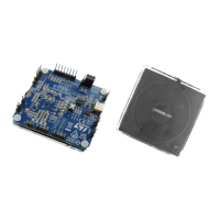
Step 8. Move the sliders on right-hand side to achieve a flat line close the target ΔP.
Figure 71. Tuning to obtain a flat BPP FOD curve
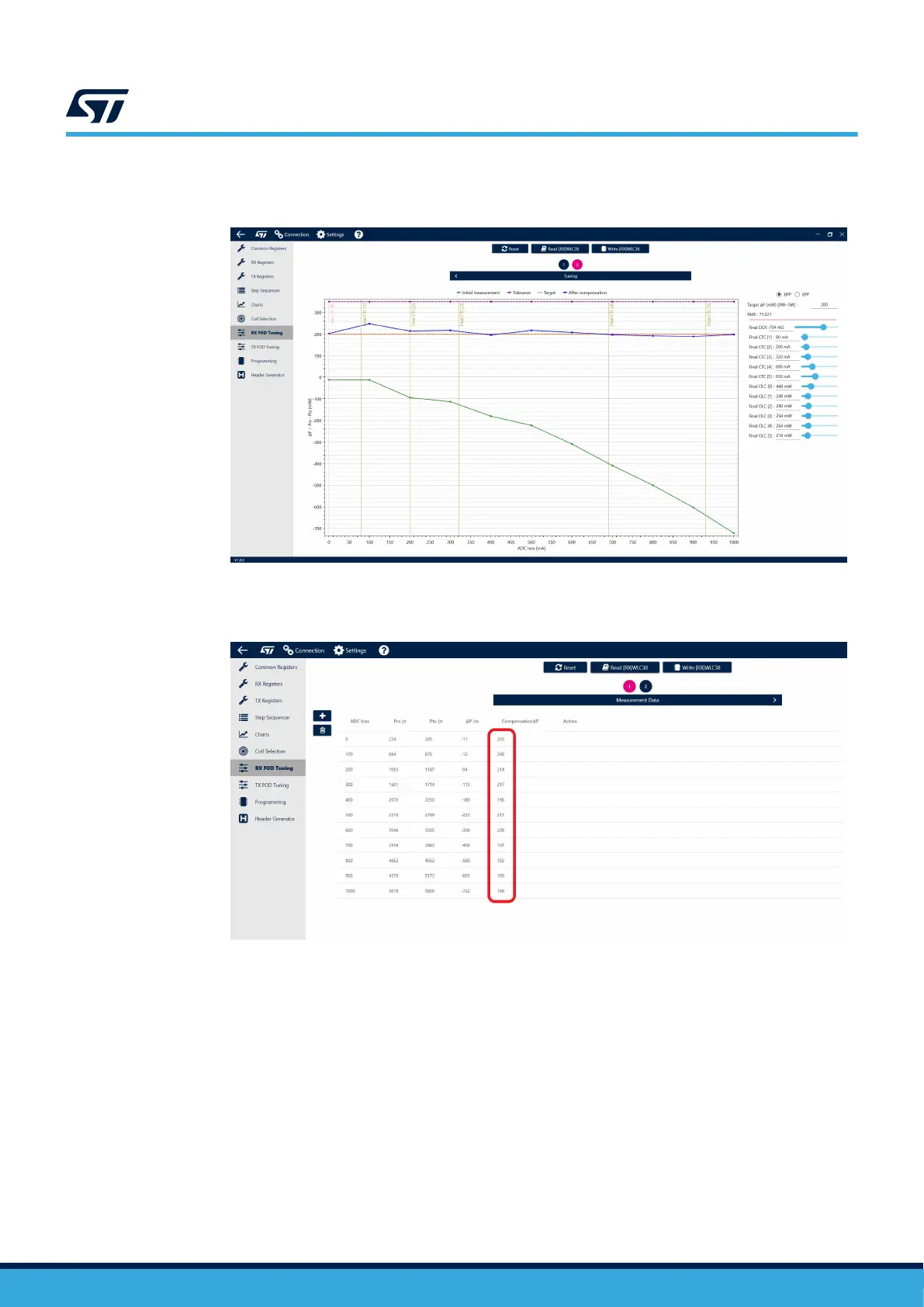
Step 9. Check the compensated values by navigating back to the first page of the tool.
Figure 72. Compensated values
Step 10. Copy the compensation values located on the right to the Rx Registers (RX BPP FOD Configuration)
and generate a new Configuration file.
Step 11. Load the Configuration file into STWLC38.
Step 12. Repeat the previous measurement under the same conditions and check if the results are the same.
Step 13.
The results will not be exactly the same as there are a lot of variables affecting the power difference
(X/Y missalignment, Z gap, transmitter measurement accuracy, STWLC38 measurement accuracy
etc.), but they should be very similar.
Step 14. Repeat the test with a 5 mm misalignment in the X and Y axis.
FOD should not be triggered by the misalignment.
UM3154
FOD tuning
UM3154 - Rev 2
page 62/81