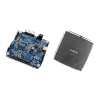
Step 6. Increase the load from 0 to 1000 mA in 100 mA steps (in case of a 5 W setup) and record the Prx and
Ptx values (use the [+] button to add more lines).
The Qi standard allows up to 350 mW difference between Prx and Ptx. The default target of the tool is
set to 200 mW (can be adjusted on the right-hand side). The lower value provides a margin which
helps prevent a false FOD trigger.
Figure 69. Load adjustment
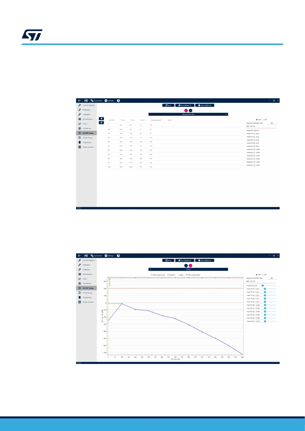
Step 7. Navigate to the second page of the tool by clicking the 2 button above.
The initial Rx/Tx power difference, labeled ΔP, is shown in green. The target of the tuning is to find
compensation values, which would move the blue (compensated ΔP) curve as close to the 200-mW
(orange dashed) line as possible.
Figure 70. Rx/Tx power difference curve
UM3154
FOD tuning
UM3154 - Rev 2
page 61/81