5.2 Integrated power rectifier
The synchronous rectifier is a key block in charge of converting the AC power signal from the receiving coil into a
DC supply rail for the following linear regulator. The rectifier consists of four N-channel MOSFET transistors
arranged into an H-bridge, conveniently driven by a control block that monitors the voltage at the AC1 and AC2
pins to optimize the commutations and to charge the external bootstrap capacitors for the high-side switches.
Different driving schemes for the rectifier switches are possible. The MCU core dynamically selects the optimal
one to maximize the overall efficiency as a function of the operating point.
When designing the filtering capacitor at the output of the synchronous rectifier, keep in mind that the capacitance
value should be designed large enough to minimize the residual AC voltage ripple and to provide sufficient energy
storage to sustain load transients and prevent the transients from impacting the ASK communication with the
transmitter.
5.3 Internal ADC channels monitor
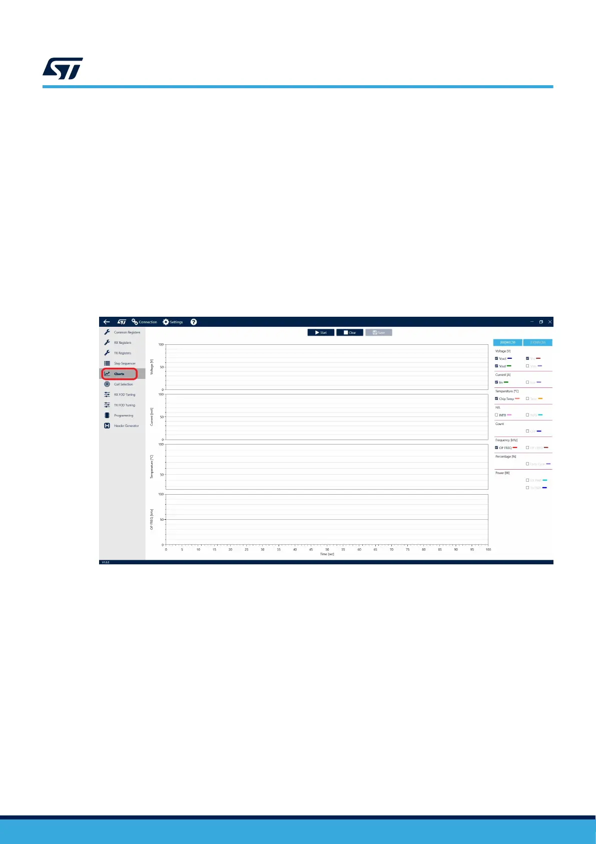
The GUI allows to monitor in real-time key parameters by reading the internal ADC channels of the STWLC38
and plotting voltages, current, and temperatures. For further details please refer to the GUI user manual
UM3164.
Figure 16. PC GUI charts
5.4 Main LDO regulator
The main LDO regulates the rectified voltage to a target value specified by the user. The output voltage is
configurable in 4 V – 12 V range with a 25 mV step. The default value of output voltage is 5 V for BPP (5W) mode
and 9 V for EPP (15W) mode respectively. However, the target value can be easily changed in the GUI or by an
external host controller.
The main LDO regulator is equipped with two protections:
1. IVL (input voltage loop): when the Vrect voltage falls under a set threshold, the Vout is temporarily disabled
until the Vrect rises above the threshold again. The default threshold for this protection is 3 V but can be
adjusted in 3.5 V to 10.5 V range with a 0.5 V step.
2. OCP (overcurrent protection): this protection is triggered when the rectifier current rises above a set
threshold. The threshold can be adjusted to a value between 1.25 A and 1.93 A.
3. RX UVLO (undervoltage protection): when V
RECT
falls under a set threshold, the set action may be triggered
as send EPT or permanent disable of V
OUT
.
4. Output short circuit protection is realized by a combination of overcurrent protection (OCP) and undervoltage
protection (RX UVLO) mechanisms.
UM3154
Integrated power rectifier
UM3154 - Rev 2
page 15/81