5.14 GPIOx and INTB pins
GPIO0 through GPIO2 are programmable general-purpose I/O pins. These pins can be configured as inputs or
outputs (push-pull or open-drain) and assigned various functions.
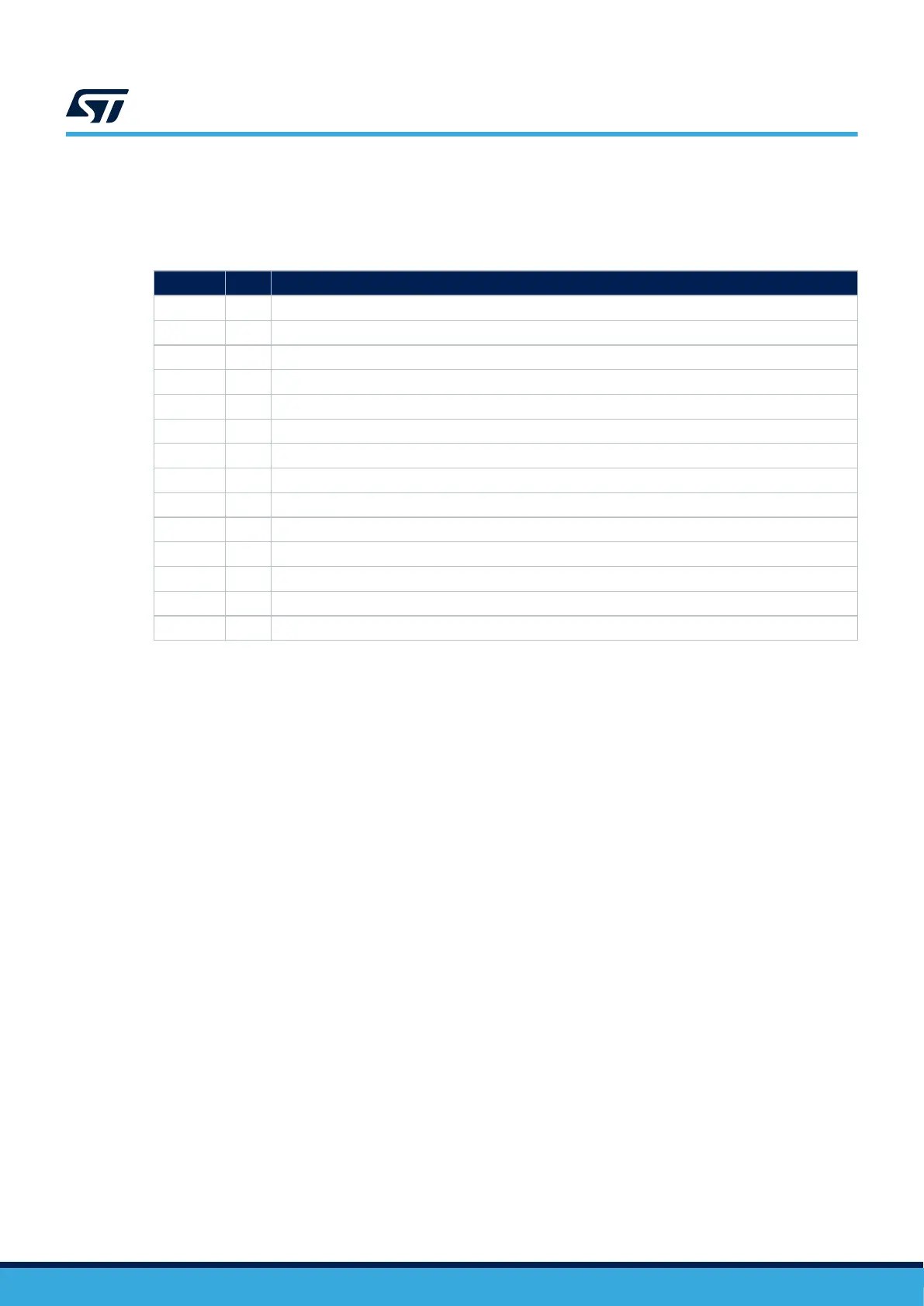
Table 6. GPIO pins
Code I/O Function
0x01 I Pull-up
0x02 I Pull-down
0x03 O Interrupt (Open drain)
0x04 O Interrupt (Push pull)
0x05 O FW ready
0x06 I Disable the main LDO
0x07 I Disable ASK communication
0x0B O Indication of successful Negotation. (Push-pull, active high)
0x0C O Indication of successful Negotation. (Push-pull, active low)
0x0D O Indication of successful Negotation. (Open drain)
0x29 O Open drain, active low
0x2A O Open drain, active high
0x2B O Push-pull, active low
0x2C O Push-pull, active high
The INTB pin is an interrupt output line that can be assigned to any internal interrupt condition and used to inform
the host system about a specific event.
5.15
Interrupt registers
There are 4 bits (enable, clear, latch and status) assigned to each interrupt sorted into separate tabs.
The enable tab can be used to either enable the corresponding interrupt (write), or to check whether the interrupt
is already enabled (read).
The latch tab can be used to determine which interrupts have been triggered (read only). After being triggered,
the bit remains set to 1 until cleared by writing a 1 into the corresponding clear register (write only).
The status tab can be used to determine which interrupt is being triggered at a given moment (read only). The
status bit goes back to zero after the triggering condition is removed.
UM3154
GPIOx and INTB pins
UM3154 - Rev 2
page 38/81