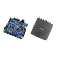
3 Overview of the Board
The STEVAL-WLC38RX evaluation board is optimized for performance. The board features:
• STWLC38 wireless power receiver chip with BPP and EPP compliant firmware
• Very few external components, optimized BOM and PCB space
• On-chip high efficiency rectifier
• Support for external NTC for thermal monitoring
• On-chip thermal management and protections
• WPC Qi extended power profile (EPP, 15 W) compatible receiver chip
•
On board USB-to-I
2
C converter
• USB Type-C® connector for PC GUI connection
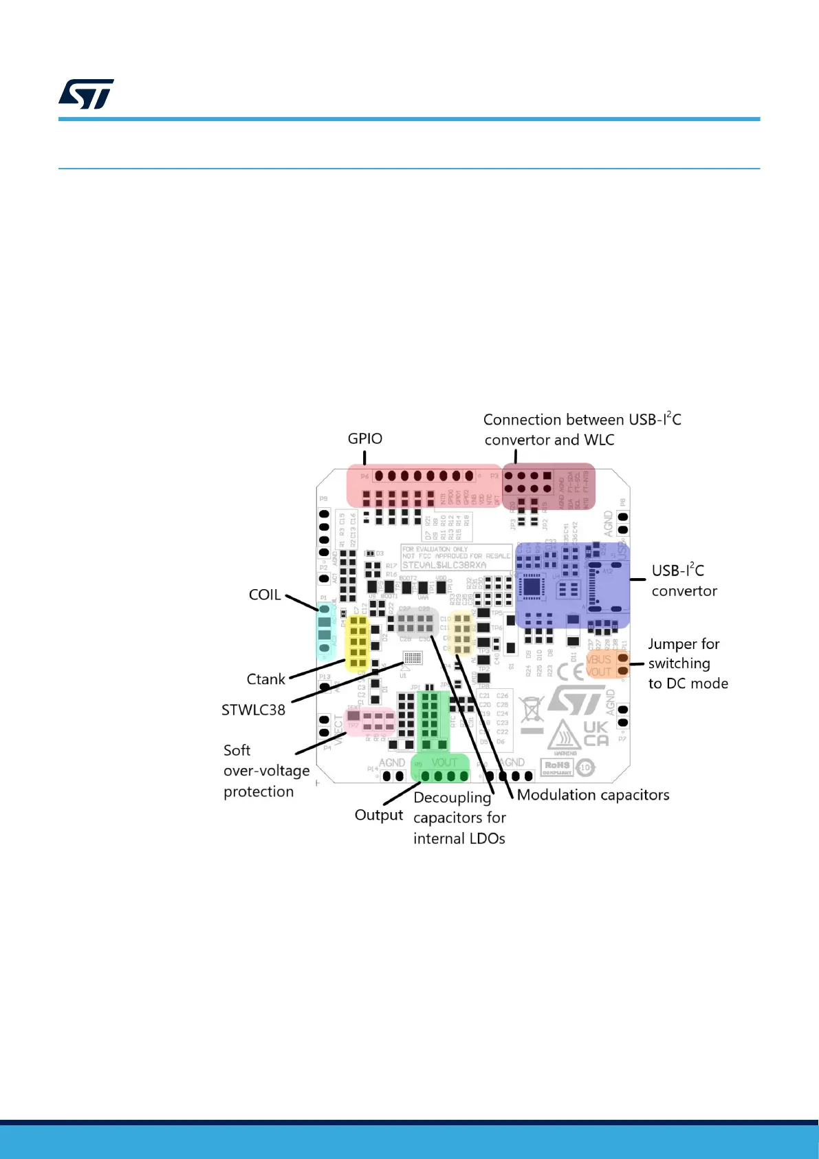
Figure 2. Main board elements
• Series resonant capacitors and the receiving coil together form a resonant circuit. This circuit is in charge
of receiving the power signal, so any components/tracks involved should be rated accordingly
• USB/I
2
C converter–provides a communication channel between a PC and STWLC38. LED D8 (Red)
indicates that the I
2
C converter is powered, D9 (yellow) indicates that STWLC38 is connected to the GUI.
LED D10 (Green) indicates that I
2
C communication was initialized and is ready. Switch S1 resets the
converter. Note that header P3 connects the converter’s I
2
C signals to the STWLC38 I
2
C signals. Short the
corresponding pins with a jumper to establish a connection between the two ICs.
• Red LED (D7)–indicates STWLC38 core power status (LED is on when the core is powered).
UM3154
Overview of the Board
UM3154 - Rev 2
page 4/81