EasyManua.ls Logo

STMicroelectronics STM32F038C6 User Manual

STMicroelectronics STM32F038C6
103 pages
To Next Page IconTo Next Page
To Previous Page IconTo Previous Page
Page #39 background image
DocID026079 Rev 3 39/102
STM32F038x6 Electrical characteristics
79
6.2 Absolute maximum ratings
Stresses above the absolute maximum ratings listed in Table 15: Voltage characteristics,
Table 16: Current characteristics and Table 17: Thermal characteristics may cause
permanent damage to the device. These are stress ratings only and functional operation of
the device at these conditions is not implied. Exposure to maximum rating conditions for
extended periods may affect device reliability.
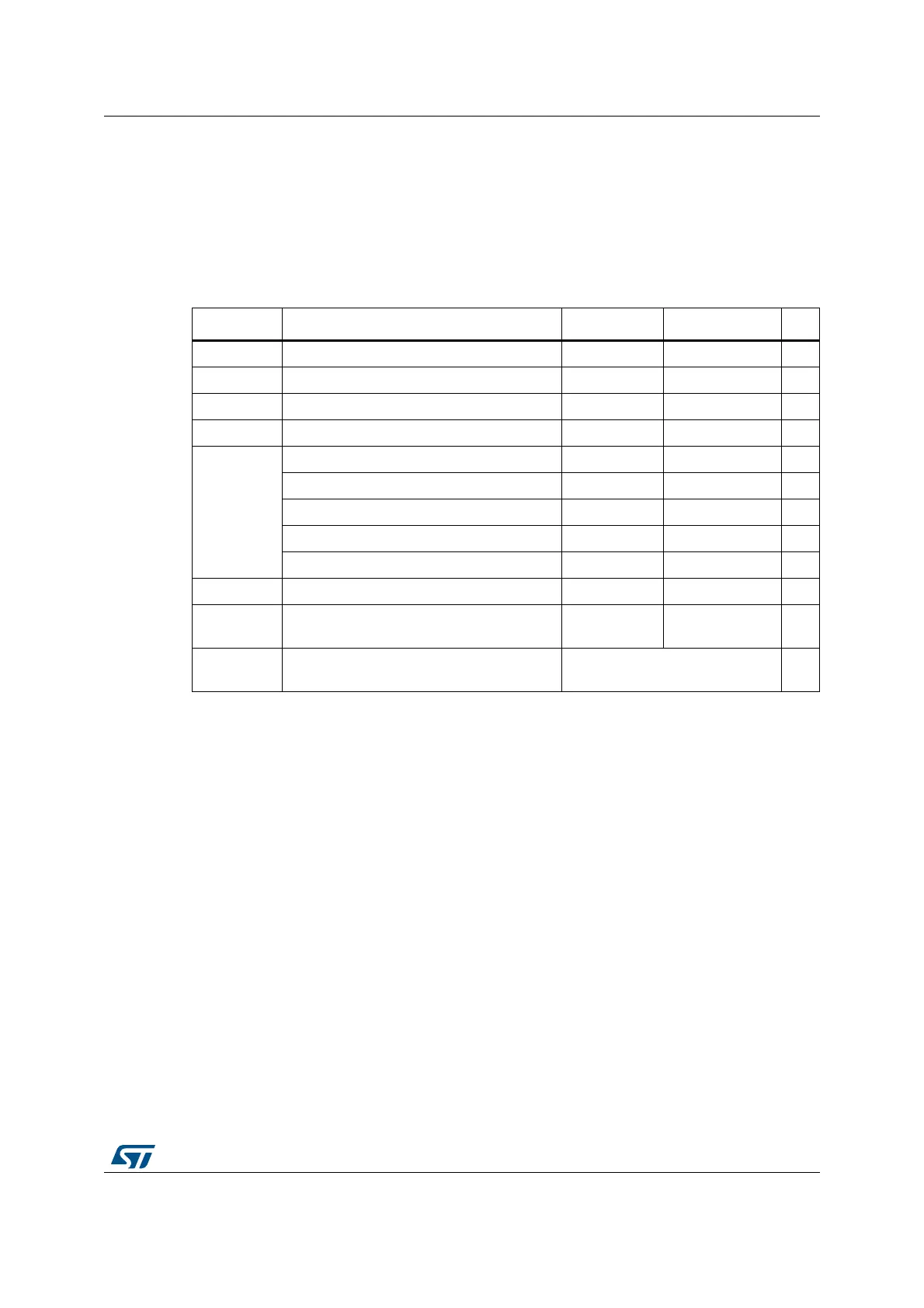
Table 15. Voltage characteristics
(1)
1. All main power (V
DD
, V
DDA
) and ground (V
SS
, V
SSA
) pins must always be connected to the external power
supply, in the permitted range.
Symbol Ratings Min Max Unit
V
DD
–V
SS
External main supply voltage -0.3 1.95 V
V
DDA
–V
SS
External analog supply voltage -0.3 4.0 V
V
DD
–V
DDA
Allowed voltage difference for V
DD
> V
DDA
-0.4V
V
BAT
–V
SS
External backup supply voltage -0.3 4.0 V
V
IN
(2)
2. V
IN
maximum must always be respected. Refer to Table 16: Current characteristicsfor the maximum
allowed injected current values.
Input voltage on FT and FTf pins V
SS
0.3 V
DDIOx
+ 4.0
(3)
3. Valid only if the internal pull-up/pull-down resistors are disabled. If internal pull-up or pull-down resistor is
enabled, the maximum limit is 4 V.
V
Input voltage on POR pins V
SS
0.3 4.0 V
Input voltage on TTa pins V
SS
0.3 4.0 V
BOOT0 0 9.0 V
Input voltage on any other pin V
SS
0.3 4.0 V
|ΔV
DDx
| Variations between different V
DD
power pins - 50 mV
|V
SSx
V
SS
|
Variations between all the different ground
pins
-50mV
V
ESD(HBM)
Electrostatic discharge voltage
(human body model)
see Section 6.3.11: Electrical
sensitivity characteristics
-

Table of Contents

Question and Answer IconNeed help?

Do you have a question about the STMicroelectronics STM32F038C6 and is the answer not in the manual?

STMicroelectronics STM32F038C6 Specifications

General IconGeneral
SeriesSTM32F0
CoreARM Cortex-M0
Operating Frequency48 MHz
Flash Memory Size32 KB
RAM Size4 KB
Number of I/Os39
ADC Resolution12-bit
ADC Channels10
Operating Temperature-40°C to 85°C
Operating Voltage2.0 V to 3.6 V
Communication InterfacesI2C, SPI, USART
PackageLQFP48

Summary

Introduction

Description

Functional Overview

Core, Memory, and Boot Modes

Details on ARM Cortex-M0 core, memory, and startup boot options.

Power and Clock Management

Power supply schemes, low-power modes, and clock configurations.

ADC

12-bit ADC with multiple channels for analog-to-digital conversion.

Timers, Watchdogs, and Communication Interfaces

Covers Timers, Watchdogs, I2C, USART, SPI/I2S.

Debug Interface

Serial wire debug port (SW-DP) for debugging.

Pinouts and Pin Description

Memory Mapping

Electrical Characteristics

Parameter Conditions and Ratings

Defines measurement conditions, min/max values, and absolute maximum ratings.

Operating Conditions and Current Consumption

Specifies operating ranges and current draw in various modes.

Clock, I/O, and Sensitivity Characteristics

Covers clock sources, I/O behavior, and electrical sensitivity.

Peripheral Specific Characteristics

Details specific characteristics of ADC, Timers, and Communication Interfaces.

Package Information

Package Types and Mechanical Data

Covers LQFP48, UFQFPN32, UFQFPN28, WLCSP25, and TSSOP20 packages.

Thermal Characteristics

Package thermal resistance and calculation of junction temperature.

Part Numbering

Revision History

Related product manuals