DocID026079 Rev 3 67/102
STM32F038x6 Electrical characteristics
79
Input/output AC characteristics
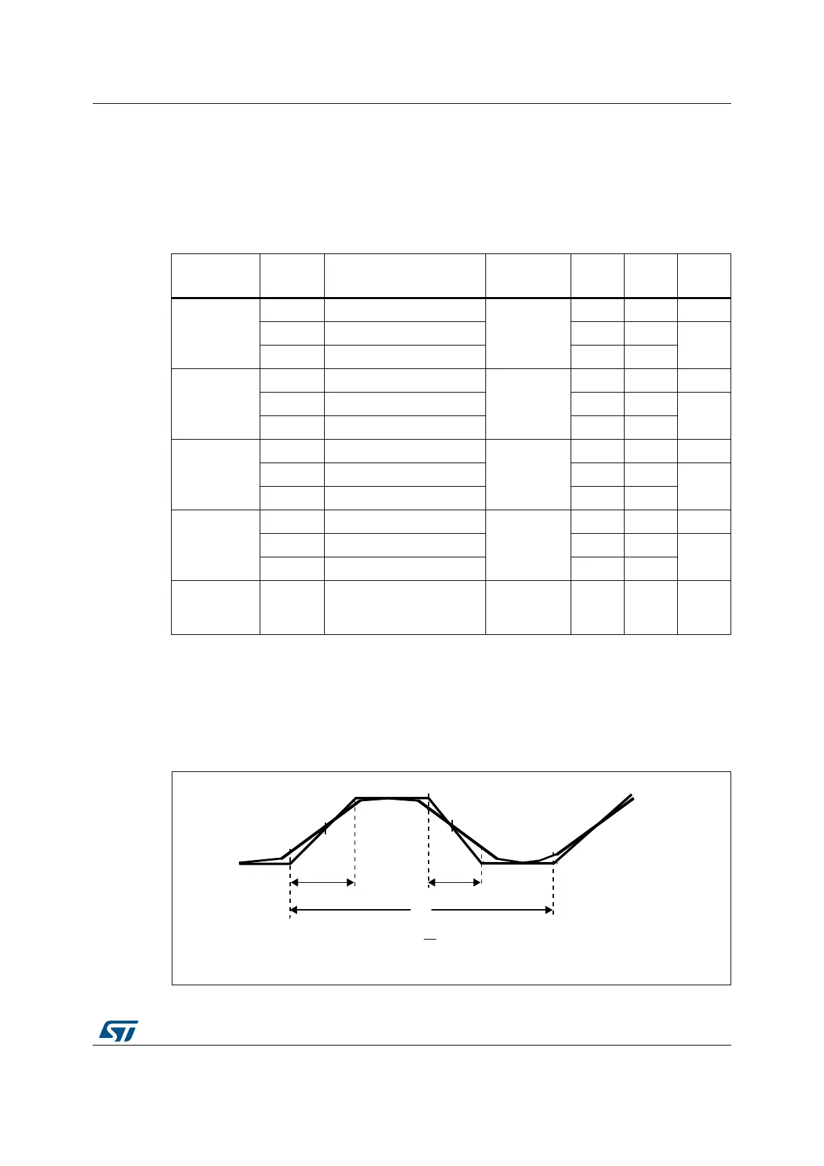
The definition and values of input/output AC characteristics are given in Figure 21 and
Table 46, respectively. Unless otherwise specified, the parameters given are derived from
tests performed under the ambient temperature and supply voltage conditions summarized
in
Table 18: General operating conditions.
Figure 21. I/O AC characteristics definition
Table 46. I/O AC characteristics
(1)(2)
1. The I/O speed is configured using the OSPEEDRx[1:0] bits. Refer to the STM32F0xxxx RM0091 reference
manual for a description of GPIO Port configuration register.
2. Guaranteed by design, not tested in production.
OSPEEDRy
[1:0] value
(1)
Symbol Parameter Conditions Min Max Unit
x0
f
max(IO)out
Maximum frequency
(3)
3. The maximum frequency is defined in Figure 21.
C
L
= 50 pF
-1MHz
t
f(IO)out
Output fall time - 125
ns
t
r(IO)out
Output rise time - 125
01
f
max(IO)out
Maximum frequency
(3)
C
L
= 50 pF
-4MHz
t
f(IO)out
Output fall time - 62.5
ns
t
r(IO)out
Output rise time - 62.5
11
f
max(IO)out
Maximum frequency
(3)
C
L
= 50 pF
-10MHz
t
f(IO)out
Output fall time - 25
ns
t
r(IO)out
Output rise time - 25
Fm+
configuration
(4)
4. When Fm+ configuration is set, the I/O speed control is bypassed. Refer to the STM32F0xxxx reference
manual RM0091 for a detailed description of Fm+ I/O configuration.
f
max(IO)out
Maximum frequency
(3)
CL = 50 pF
-0.5MHz
t
f(IO)out
Output fall time - 16
ns
t
r(IO)out
Output rise time - 44
t
EXTIpw
Pulse width of external
signals detected by the
EXTI controller
10 - ns
069
7
0D[LPXPIUHTXHQF\LVDFKLHYHGLIWW
ZKHQORDGHGE\&VHHWKHWDEOH,2$&FKDUDFWHULVWLFVGHILQLWLRQ
UI
U,2RXW
W
I,2RXW
W
-
7DQGLIWKHGXW\F\FOHLV