DocID026079 Rev 3 37/102
STM32F038x6 Electrical characteristics
79
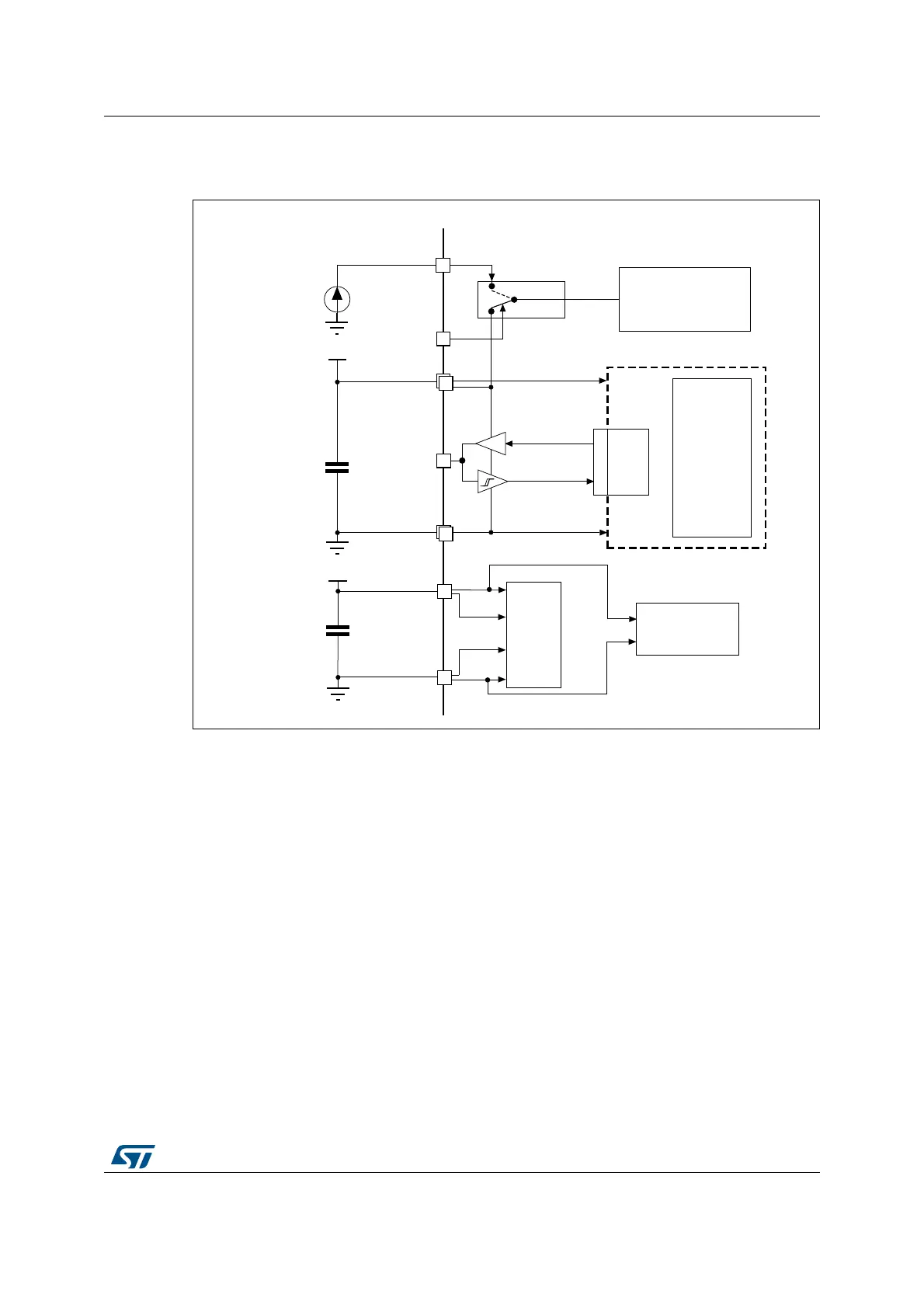
6.1.6 Power supply scheme
Figure 11. Power supply scheme
Caution: Each power supply pair (V
DD
/V
SS
, V
DDA
/V
SSA
etc.) must be decoupled with filtering ceramic
capacitors as shown above. These capacitors must be placed as close as possible to, or
below, the appropriate pins on the underside of the PCB to ensure the good functionality of
the device.
9
''
/HYHOVKLIWHU
,2
ORJLF
.HUQHOORJLF
&38'LJLWDO
0HPRULHV
%DFNXSFLUFXLWU\
/6(57&
%DFNXSUHJLVWHUV
,1
287
*3,2V
±9
[Q)
[)
[9
66
[9
''
9
%$7
9
&25(
3RZHUVZLWFK
1325
9
'',2
$'&
$QDORJ
5&V3//«
9
5()
95()
9
''$
Q)
)
9
''$
9
66$
06Y9