EasyManua.ls Logo

STS 1656 - PLC Signal Levels; System Functions; Environmental; Table 2-2: PLC Option Signals - Maximum Ratings

Default Icon
88 pages
Print Icon
To Next Page IconTo Next Page
To Previous Page IconTo Previous Page
Loading...
1656 & 1657 Battery Element Tester Owner’s Manual
STS Instruments Page 13 of 88
Note: Do NOT use VGA monitor cables to connect to the PLC interface as one or more pins on these cables are
shorted to ground. Instead, use a straight-through HD DE15 to HD DE15 cable. Example L-Com model
CHD15MF-5 male/female cable or equivalent.
2.4.2 PLC Signal Levels
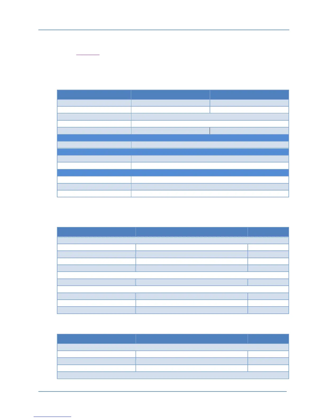
Output voltage levels and current capability for each output are shown in the table below. Do
not exceed these rating or damage to the instrument may occur.
Relay Outputs Resistive Load Inductive Load
Rated Load
AC: 125V, 0.5A
AC: 125V, 0.3A
DC: 30V, 2A
DC: 30V, 1A
Maximum Current
3A
Contact Voltage Max.
AC: 250V, DC: 220V
Contact Current Max.
2A
1A
Analog Level
Input Range = 0.0Vdc to 3.3Vdc
Voltage Level
low = 0Vdc, high = 5Vdc
Current Max.
6 mA
Pin 10: Voltage
5 Vdc
Pin 10: Current Max
1.5 Adc
Pin 5
Return Power / Ground
Table 2-2: PLC Option Signals - Maximum Ratings
2.5 System Functions
Parameter Specification Notes
Type
High Contrast Graphical Color TFT LCD
Size
4.2” diagonal
Resolution
480 x 272 (HVGA)
Backlight
White LED
Type
Rotary Digital Encoder
Type
Momentary Push Buttons
Reset Button
Illuminated Push Button, Green
Check Button
Illuminated Push Button, Red
2.6 Environmental
Parameter Specification Notes
Operating
32 to 104° F/ 0 to 40°C
Storage
-2 to 158° F / -20 to 70° C
Cooling
Convection

Table of Contents

Other manuals for STS 1656