1656 & 1657 Battery Element Tester Owner’s Manual
STS Instruments Page 23 of 88
4 Theory of Operation
This section provides background information on the test methodology used by the 1656/1657
Battery Element Tester.
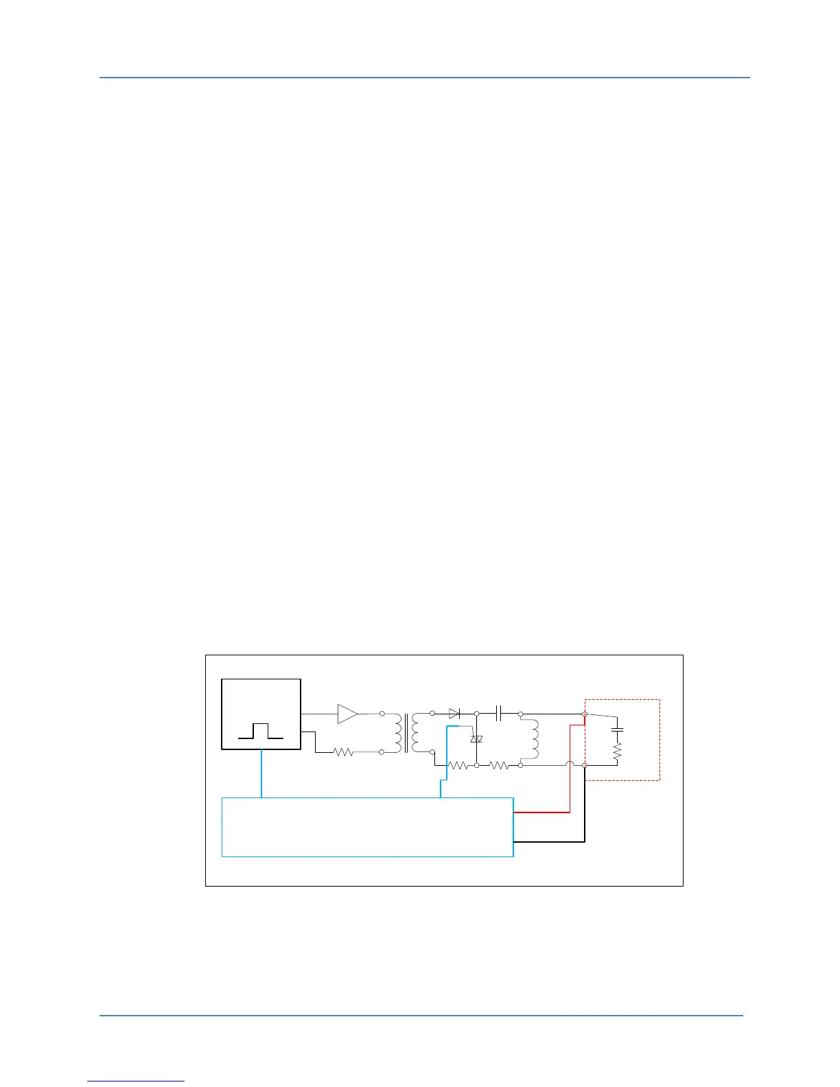
4.1 Test Pulse Generation
The 1656/1657 generates a short duration, high voltage spike at its output by quickly
discharging a charged capacitor that has been pre-charged. This capacitor is charged to the set
test voltage level using a half wave rectified DC supply operating from a high voltage step-up
transformer. The digital controller sets the primary voltage level of this transformer using a DAC
based on the user’s programmed set point. This provides an accurate and repeatable test
voltage waveform at the output of the 1656/1657test leads.
The discharge capacitors are charged on the negative half cycles of the AC line input. On the
alternate half cycles, a Silicon Controller Rectifier (SCR) is triggered by the digital controller so
that the capacitor is discharged into the load while the main charging circuit is in a non-
conducting condition. The digital measurement system uses precision Analog to Digital
converters (ADC’s) to digitize the resulting output voltage waveform. This data is processed by
the microcontroller (MCU) to verify the applied test voltage is correct.
An internal bleed load-switching coil is connected across the output terminals of the unit to
produce a fixed load condition while the unit is operating under standby (no load) conditions.
4.2 Back EMF Measurement
Under normal conditions, discharge of the capacitors into the internal coil creates a strong
magnetic field in the core of this inductor load. When the forward pulse dies off, this magnetic
field collapses producing a back Electro Magnetic Force (EMF) which is captured by the digital
controller’s measurement read back circuits. An average peak voltage read back value is
obtained over a number of successively applied test pulses.
Digital Pulse
Generator
MCU Digital Board
High Voltage
Transformer
Diode
SCR
Coupling Cap.
Trigger
R
R
Buffer
R
Internal
Coil
HV Terminals
R
C
Battery
Element
(UUT)
Measurement
Inputs
Figure 4-1: Equivalent Battery Element Tester Schematic
Any external load, such as a battery cell under test, is effectively in shunt with the internal bleed
load coil (as shown in Figure 4-1) and therefore, will reduce the back EMF signal, resulting in a