1656 & 1657 Battery Element Tester Owner’s Manual
STS Instruments Page 47 of 88
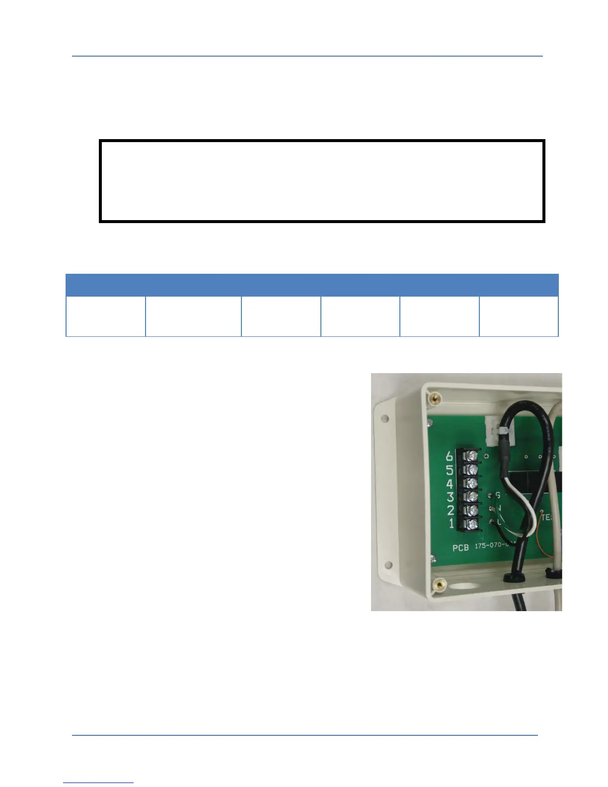
7.1.6 Internal 070 Adaptor Connections
To connect AC power, Test Input and Reject Output wires to the 995-017-907B Adaptor module,
the top cover must be removed. This can be done by removing the four screws in each cover
using a Phillip screwdriver.
WARNING
NEVER operate the 070 Adapter with the top cover removed as potential
dangerous 115Vac Voltage is present on energized circuits
The following inputs and outputs are provided on the six position compression terminal strip
located on the left hand side of the adapter module.
INPUT
INPUT
Ground
(GROUND)
Test AC High
INPUT
Reject AC High
OUTPUT
No
Connection
Table 7-1: 995-017-907B Adaptor Terminal Block Connections
The following connections must be made to the 070
internal terminal strip:
• AC Input Voltage: Nominal 115 volt 50/60 Hz input
power is required on Terminal 1 (A.C. High Input) and
Terminal 2 (A.C. Low or Common Input).
• Ground: Terminal 3 is Ground.
• Test Input AC: An application of a nominal 115 volt
(A.C. High Input) to Terminal 4 will initiate and
maintain the test voltage.
• Reject Output AC: A nominal 115 volt (A.C. High
Output) Reject Signal will appear at Terminal 5
whenever the tester is indicating a reject.
• No Connection: Terminal 6 is not used.
When all connections have been made, the top cover must be re-installed. The adaptor module
is now ready for use.