1656 & 1657 Battery Element Tester Owner’s Manual
STS Instruments Page 28 of 88
Indicators Description
This is the main display area of the instruments. All settings and
readings are displayed on the main LCD screen uses a variety of
menus and measurement/test screens.
The 1656 has two Reject Indications; an Audible Tone and a 15-
pin HD D-sub PLC interface connector on the rear panel which
provides a Dry Contact Closure when a reject occurs.
Indicates instrument is in LOCKED state (Controls are Locked
out). A password entry is required to unlock the front panel.
Refer to section 5.9, “Password Information” for details.
Indicate instruments in being controlled remotely over one of its
digital control interfaces.
Connectors Description
CONNECTORS
Two (2) High Voltage connectors are provided on the front
panel. Polarity should be observed when connecting the leads.
The black socket is referenced to ground.
Test Lead High Voltage Mating Connector, RED
Test Lead High Voltage Mating Connector, BLACK
The –RPC option adds rear panel High Voltage connectors to the
1656 unit.
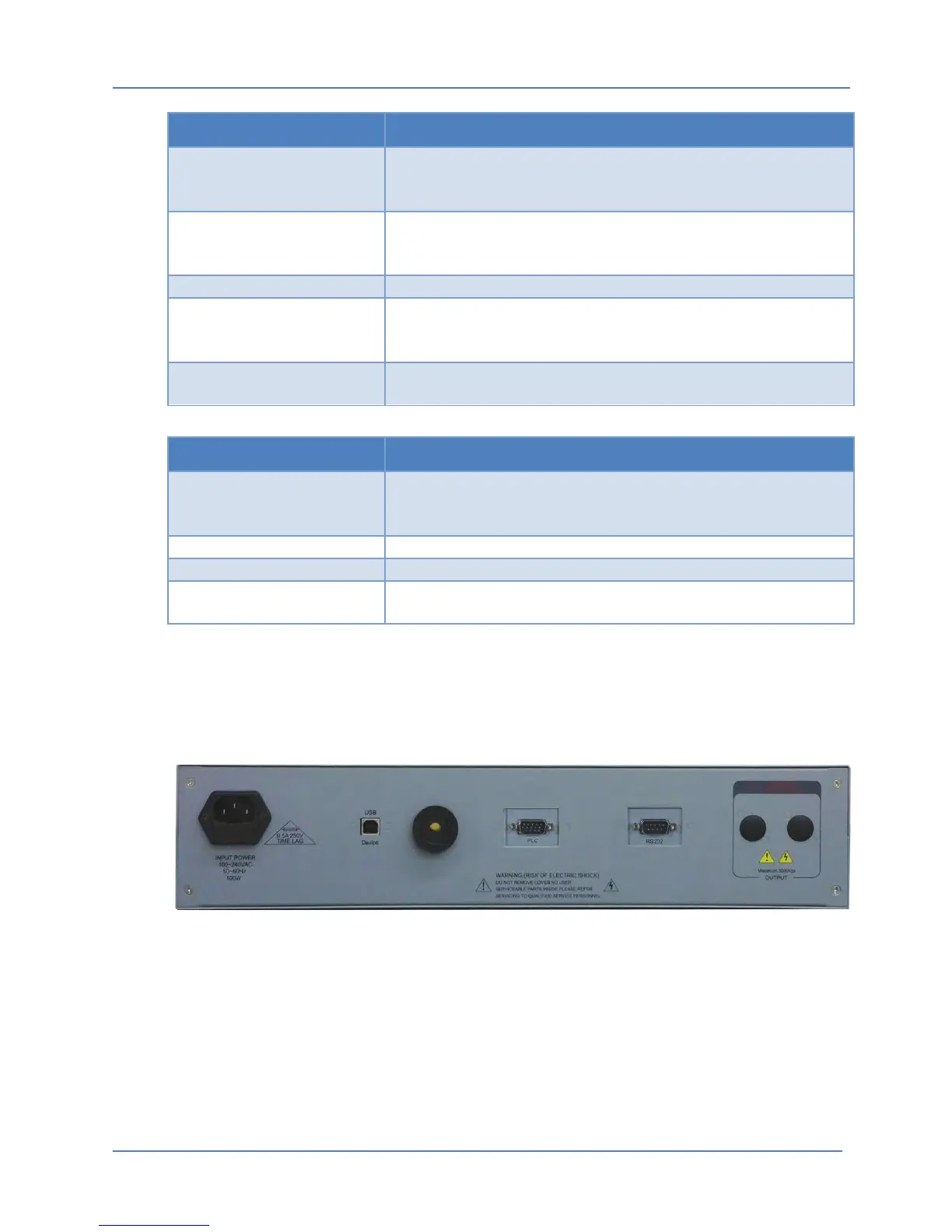
5.2 Rear Panel Connectors
The available connectors located on the rear panel of the 1656 Battery Element Tester are
shown in the Figure below.
Figure 5-3: Rear Panel Connector Locations (shown with PLC Interface and -RS232 option)