Micro Series
1-6 Micro Series
Document generated: 29.06.17
SW V1.1
1.2.2 Micro Fader
Up to two Micro Fader modules can be connected to one Micro Core - giving
access to up to 12 faders. This allows professional Radio OnAir operation.
Connection is via a single cat5 cable for communication protocol and power.
1.2.2.1 Operating Elements
There are six non-motorized faders. Each channel strip has its own display
Per channel strip, two small option buttons are placed directly below the
display. Further down, two large buttons are placed above the fader. These
buttons are used for Rec an Cue functions. Then below the fader there are
another two large buttons : the On- and the PFL /Off button.
Also a signal indication- as well as an overload LED are placed between the
fader and the upper two large buttons.
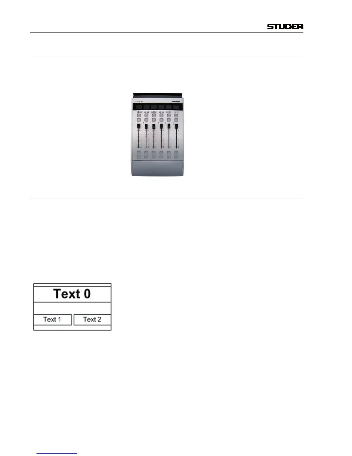
Display The Micro Fader module provides a two row LCD display to indicate :
•theeightcharacterchannellabelonthefirstrow(Text0),
•thefunctionsofthechannelspecificbuttonsonrrrrthesecondrow.
( The background of the function name is inverted when the function is active.)
•ChannelOn-Masterstatus,bychangingthebacklightcolourfromwhite
(default) to blue. The backlight is flashing if a channel that is On-Master is
pending on snapshot parameter recall.
Buttons The Micro Fader module features six buttons per channel strip. From top to
bottom of the strip, they have the following functions :
•Twosmallbuttonsdirectlyunderneaththedisplay.Theirfunctionsareshown
on the lower row of the display. (Text 1 and Text 2)
•TheREC button is the same as the REC button in the GUI. This button
contains one yellow LED . The OffAir Record function is indicated yellow.
•TheCUE/Blank button. This button contains two LEDs, red and yellow.
(The CUE function is indicated yellow).
•TheON button is the same as the ON button in the GUI. This button contains
two LEDs, red and yellow.The Channel ON status is indicated red.
•ThePFL/OFF button.This button contains two LEDs, red and yellow. The
PFL function is indicated yellow, the OFF function not illuminated.