Micro Series
Micro Series 1-79
Document generated:29.06.17
SW V1.1
of the Micro Fader module, all of the changed settings will be applied.
Note : It is necessarry to change the IP address of one Micro Fader module, if two
Micro Fader modules are to be used together. (This needs to be done before
the Micro Fader modules can be assigned to the Micro Core.)
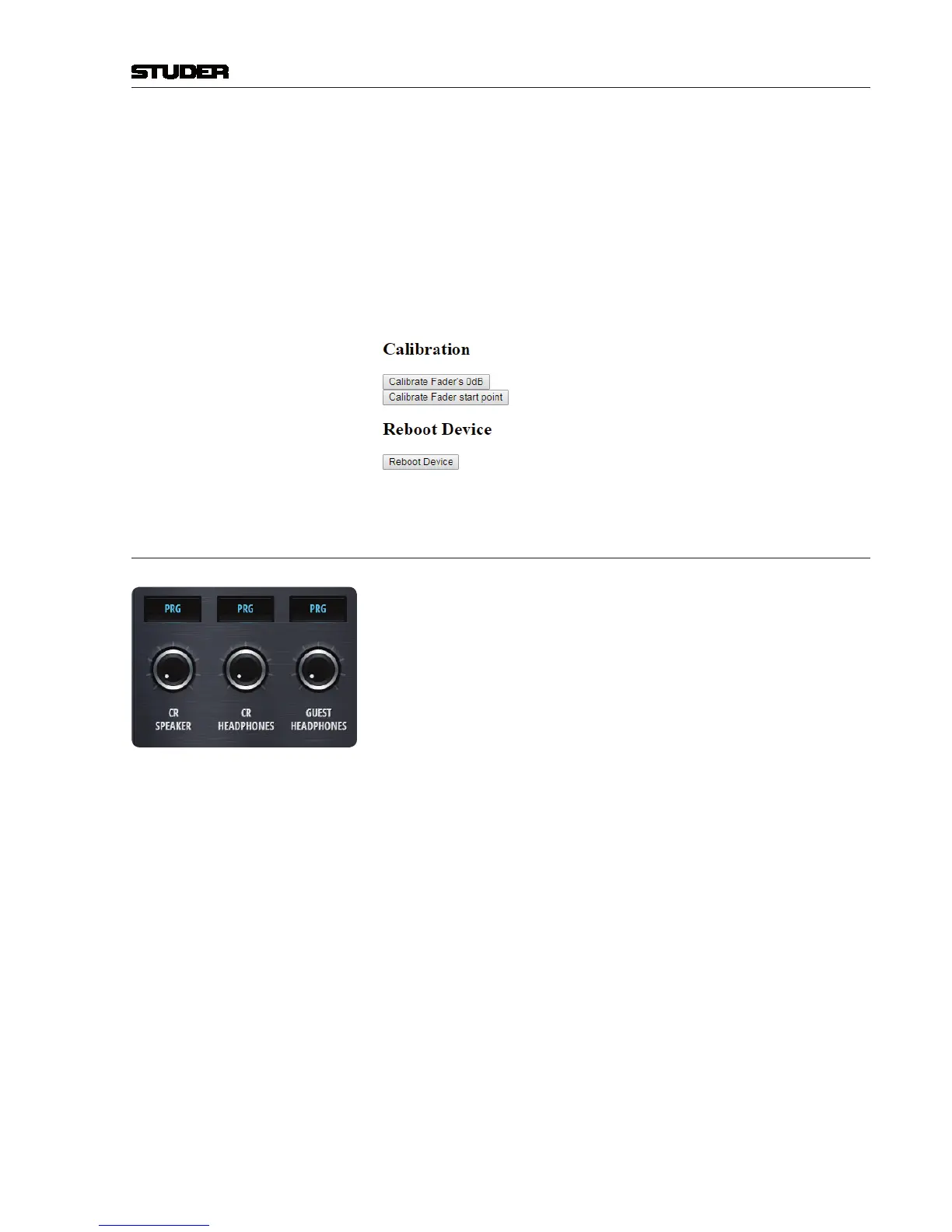
Fader Calibration The fader’s 0dB position can be calibrated.
And the fader start point can also be calibrated - which is the position where
the fader start signal is triggered when opening the fader from -infinity
towards 0 dB.
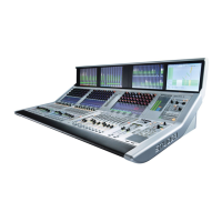
3.3 Setting up the Monitoring
In total, there are two monitoring sections that can be used within the Micro
Core.
•TheCRMonitoringsection(withboth,loudspeakerandheadphonesoutputs)
•TheGuestHeadphonesection(withheadphonesoutputonly)
The actual physical outputs that are used by these two monitoring sections
can be freely assigned.
Step 1 Chose the monitoring section that you would like to configure.
Step 2 What should be connected ?
- Active loudspeaker
- Headphone
- Meter
Step 3 What physical connector ?
Step 4 Assign the output :
This is done on the CR Config page, on the Targets tab.
Any of the outputs viewable on this page can be used :
•12LineOutputs
•8DanteOutputs
•2AESStereoOutputs
•2UnbalancedJackStereoOutputs