67
Chapter 4: Motherboard Connections
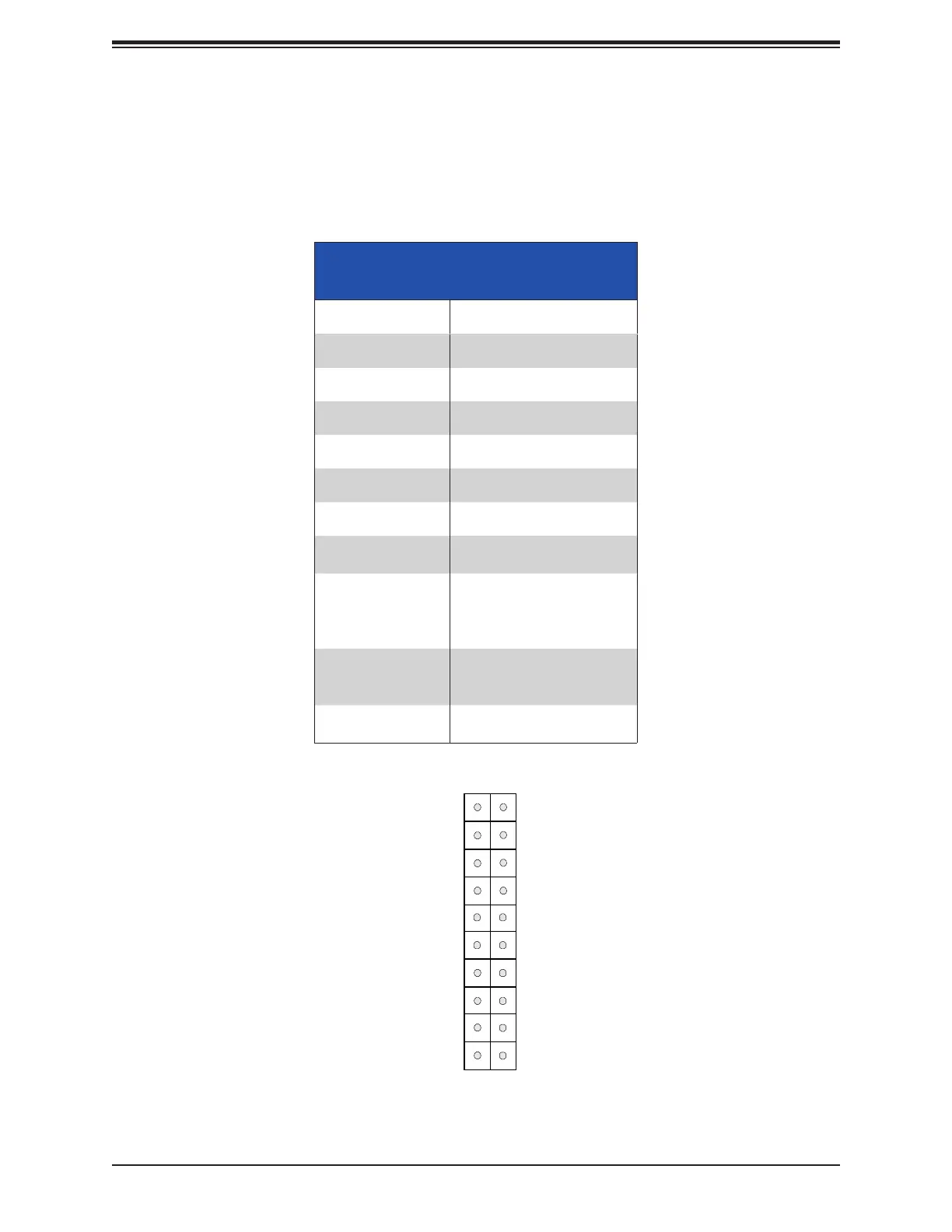
Figure 4-2. JF1 Control Panel Pins
Control Panel
JF1 contains header pins for the front control panel connections. All JF1 wires have been
bundled into a single cable to simplify this connection. Make sure the red wire plugs into pin
Power Button
(Blue LED_Cathode_UID)
NIC1 (Activity) LED
Reset Button
HDD LED
FP PWR LED
ID_UID/3.3V Stby
Ground
19
Ground
20
1 2
Ground
Power Fail (for LED6)
NIC2 (Link) LED
NMI
3.3V
(Red OH/Fan Fail/PWR Fail for LED5/Blue UID LED)
3.3V
JF1
Red+ Blue+
NIC2 (Activity) LED
NIC1 (Link) LED
Key
Key
Front Control Panel (JF1) LED
Indicators
Event Pwr LED
Power On Solid On
NIC Activity
Overheat
Fan Fail
Power Fail
Recovering/
Updating
Check Failed
Mode