DISASSEMBLY AND ASSEMBLY
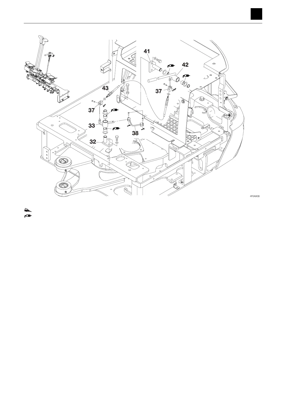
OPERATING DEVICE
2
4
OPERATING DEVICE 4F0AX00
ThreeBond #1324
Apply grease to the inside surfaces of the DU bushing during assembly.
1 Adjust the pedal so that it is not de-
pressed at a position away from the
center.
2 After putting together the machine
lever assembly, check the opera-
tion of the travel lock section and
sliding plate.
3 Adjust the lever so that it is oriented
at a right angle when set to neutral.
1. Bracket 17. Bracket 33. Lever
2. Mini pillow bearing unit 18. Lock cylinder 34. Bracket
3. Lever 19. Plate 35. Elbow
4. Lever 20. Plate 36. Elbow
5. Lever 21. Plate 37. Yoke
6. Travel lever R 22. Bracket 38. Bracket
7. Travel lever L 23. Pedal 39. Plate
8. Shaft 24. Pedal 40. Bracket
9. Mini pillow bearing unit 25. Rod end 41. Bracket
10. Shaft 26. Rod end 42. Lever
11. Lever 27. Set screw 43. Control cable
12. Lever 28. Yoke R 44. Lever
13. Lever 29. Lever 45. Rod
14. Lever 30. Yoke L 46. Bracket
15. Lever 31. Rod
16. Lever 32. Bracket
 Loading...