FUNCTION
TRAVEL MOTOR
1
3
TRAVEL MOTOR 3M0AX00
TRAVEL MOTOR
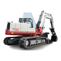
Hydraulic motor
The cylinder block (1) is formed of the pistons (2), and its
end surface comes in contact with the valve plate (3) that
contains the two half-moon-shaped ports B and C. The
cylinder block (1) rotates freely and is connected to the
drive shaft (4) via the splines. Meanwhile, the swash
plate (5) is secured to the housing.
When the high-pressure oil is directed to the port B, the
pistons (2) push against the swash plate (5) with a force
F per piston.
F = P × A, where P: Pressure, A: Cross-sectional area of
piston
The pushing force F applied against the swash plate (5)
by the pistons (2) has two components: a force F1 com-
ponent that pushes against the swash plate and a force
F2 component that rotates the cylinder block (1). The to-
tal sum of the components in the direction of rotation of
the piston on the high-pressure side generates a rota-
tional force in the cylinder block (1), resulting in the
torque being transmitted to the shaft (4) via the splines,
causing it to turn. Conversely, if high-pressure oil is in-
stead introduced into the port C, rotation will occur in the
reverse direction of that described above.
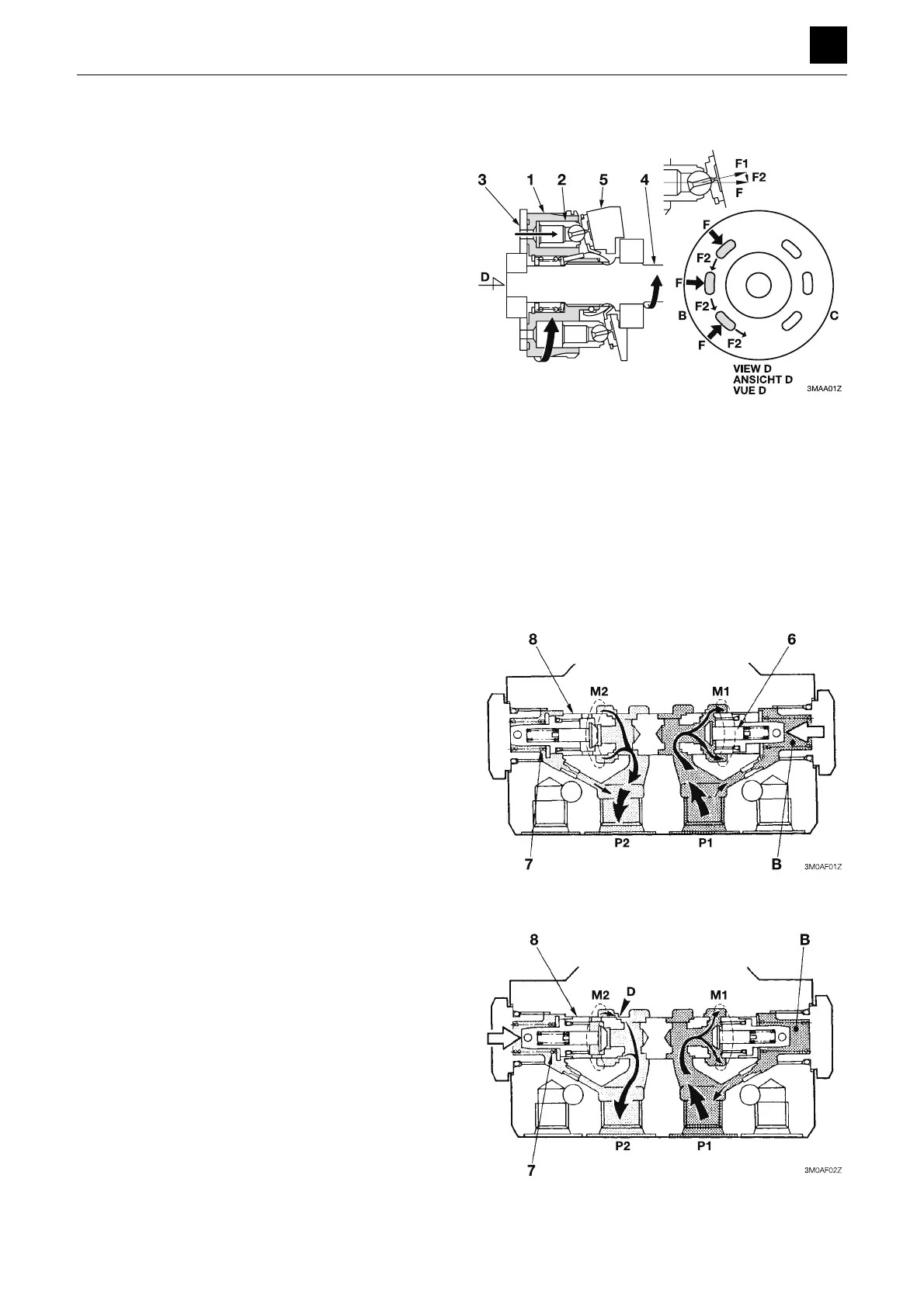
Counterbalance valve
When the high-pressure oil is directed into the port P1,
the oil pushes the check valve (6) upward and then flows
into both the motor port M1 and the chamber B in the pilot
section. The pressure oil flows into the motor from the
motor port M1. By contrast, the return oil from the motor
does not flow into the port P2 because the passage be-
tween the motor port M2 and the port P2 is blocked by
the check valve (6), which causes the pressure in the
port P1 and chamber B to rise. When the pressure in the
chamber B rises to exceed that of the set value for the
spring (7), the spool (8) is moved to the left to connect the
motor port M2 with the port P2. This causes the motor to
start running.
If the motor speed becomes too fast and the volume of
oil flowing out of the motor port M2 becomes greater than
that flowing into the motor port M1, the pressure in the
port P1 and chamber B will drop. When the pressure in
the chamber B drops to a value lower than the set pres-
sure value of the spring (7), the spool (8) attempts to
move back to the right. As a result, the flow of the return
oil is narrowed down at the section D to generate a back
pressure in the motor port M2 and slow down the motor
speed. If the motor speed decreases, the pressure in the
port P1 and the chamber B again rises, causing the
spool (8) to move to the left. The back pressure generat-
ed in the motor port M2 is then eliminated. As thus de-
scribed, the motor is controlled to run at a speed propor-
tional to the volume of the oil flowing into it.
 Loading...