FUNCTION
CONTROL VALVE
2
3
CONTROL VALVE 3J0AX00
Main relief valves
A main relief valve is mounted between the pump circuit
and tank circuit of each inlet housing and works to main-
tain the circuit pressure at the set value.
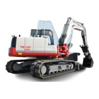
The relief valve remains turned off:
As long as the pressure in the circuit is lower than the set
pressure, the relief valve will maintain the pressure equi-
librium and remain shut off. The hydraulic pressure from
the pump passes from the chamber C into the orifice of
the main poppet (2) and then on until it reaches the
chamber D and needle valve (1). Meanwhile, the forces
F and F1 act on the sides of the main poppet (2), as indi-
cated by the arrows.
F = P × A
F1 = P × A1 (P: Pressure, A and A1: Cross-sectional ar-
eas)
The cross-sectional area A1 is larger than the cross-sec-
tional area A, which causes the main poppet (2) to be
pushed to the left seat surface by the force of F1 - F.
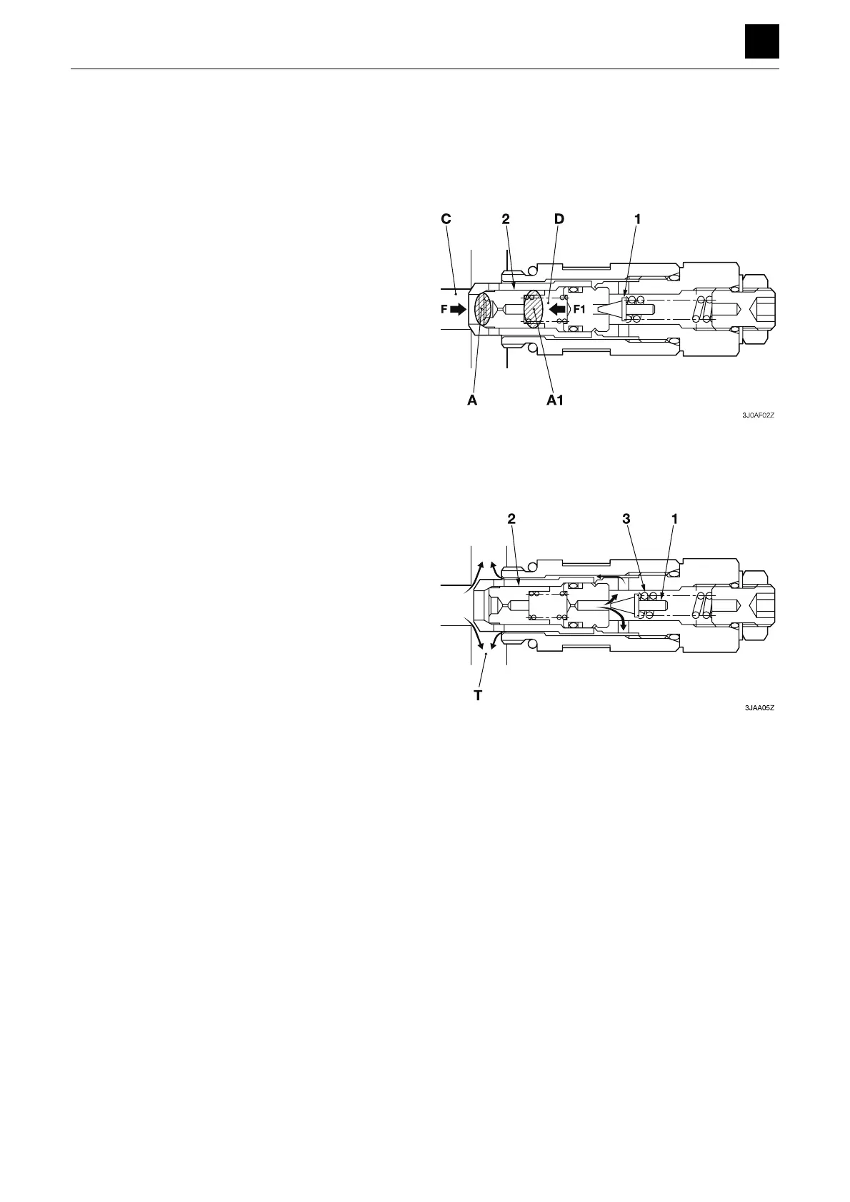
The relief valve is activated:
If the pressure in the circuit becomes higher than the set
pressure of the spring (3), the needle valve (1) will be
pushed to the right by hydraulic pressure, which will
cause the oil to flow into the tank passage T. When this
happens, a pressure differential is generated between
the two ends of the orifice of the main poppet (2), which
causes the main poppet to be pushed to the right by the
hydraulic pressure. As a result, the pressure oil in the cir-
cuit flows into the tank passage as shown by the arrows.
This operation works to maintain the pressure in the cir-
cuit at the set value.
 Loading...