DISASSEMBLY AND ASSEMBLY
TRAVEL MOTOR
4
4
TRAVEL MOTOR 4M0AX00
Assembly
The assembly procedures are given below. For disas-
sembly, follow the same procedures as for assembly but
in the reverse order by referring to the construction dia-
gram.
Counter balance valve and hydraulic motor
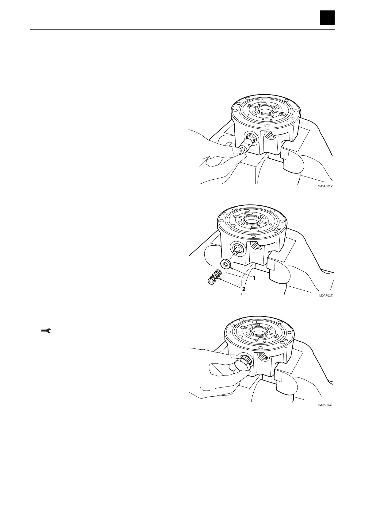
1. Secure the valve body in a vise, and insert the spool
into the valve body.
• Insert an aluminum plate or the like between the
motor and the vise to prevent the outer surface of
the valve body from becoming damaged.
• Do not further disassemble the spool assembly.
2. Attach the rings (1) and springs (2) to both ends of
the spool.
3. Attach the O-rings to the plugs, and tighten the plugs
on both ends of the body.
Plug: 127 to 167 N·m (93.7 to 123.2 ft.-lb)
 Loading...