12
4
CONTROL VALVE
DISASSEMBLY AND ASSEMBLY
4J0AX00CONTROL VALVE
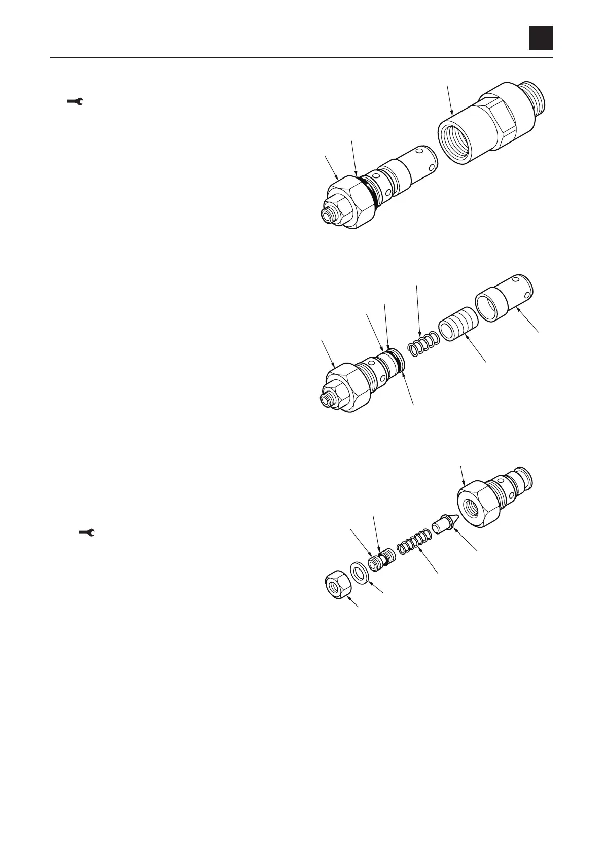
Main relief valve
1. Remove the plug (1) from the housing (2).
Plug: 49 to 54 N·m (36.1 to 39.8 ft-lb.)
2. Remove the O-ring (3) from the plug (1).
3. Remove the sleeve (4) from the plug (1), and then re-
move the spring (5) and the main poppet (6) from the
sleeve (4).
4. Remove the O-ring (7) and the backup ring (8) from the
seat (9).
5. Remove the lock nut (10), the washer (11) and the set-
screw (12) from the plug (1), and then remove the O-
ring (13) from the setscrew (12).
• Whenassembling,rstinstallthesetscrew(12),and
then temporarily fasten the lock nut (10) to adjust
the pressure before final tightening.
Lock nut: 27 to 32 N·m (19.9 to 23.6 ft-lb.)
6. Remove the spring (14) and the needle valve (15).
 Loading...