SERVICE DATA
HYDRAULIC CIRCUIT DIAGRAM
4
2
HYDRAULIC CIRCUIT DIAGRAM 2F0AX001
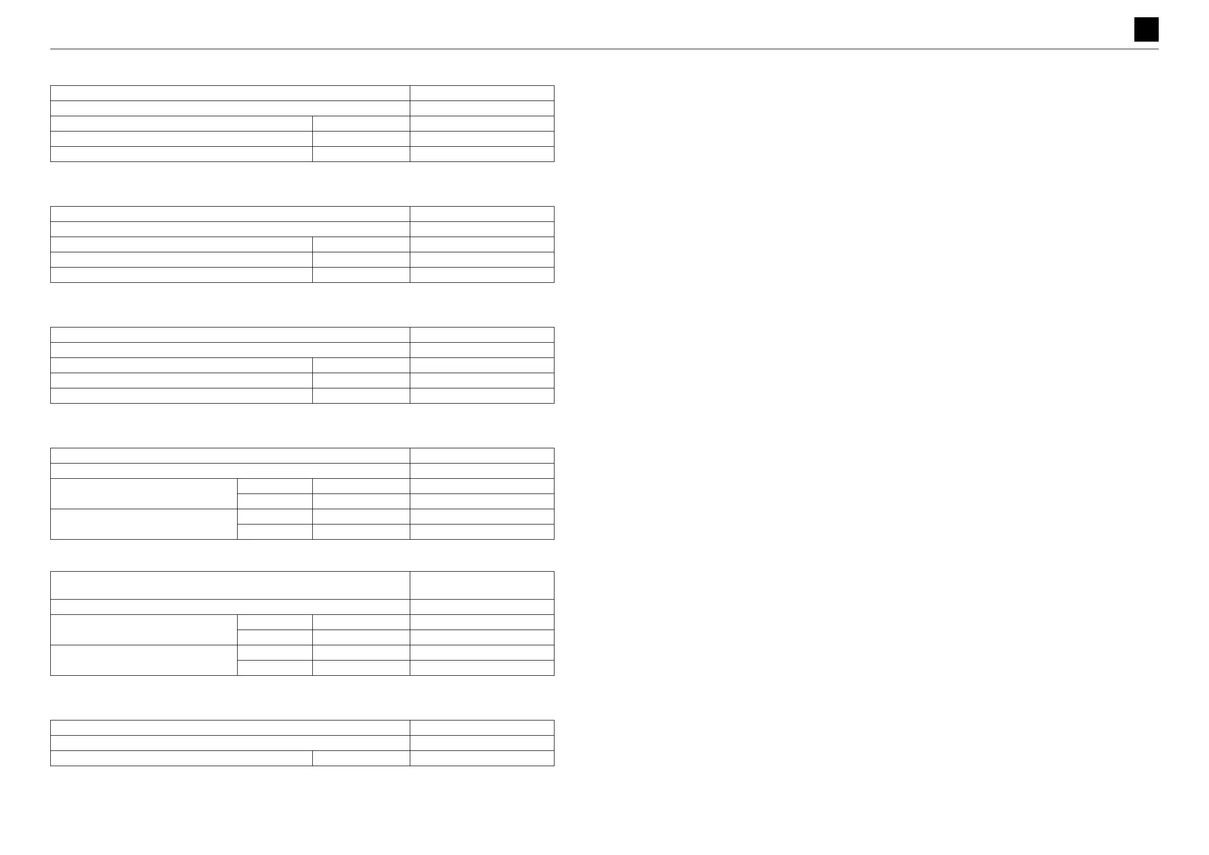
Swing cylinder
* Length from the center of the pinhole on the tube side to the center of the pinhole on the rod side
Dozer blade cylinder
* Length from the center of the pinhole on the tube side to the center of the pinhole on the rod side
Spanner cylinder
* Length from the center of the pinhole on the tube side to the center of the pinhole on the rod side
Pilot valve (R)
Pilot valve (L)
*Equipped with trigger button
Solenoid valve (2nd auxiliary line piping)
Part number 19001-16000
Type –
Bore diameter × rod diameter mm (in.) 60×35 (2.4×1.4)
Stroke mm (in.) 340 (13.4)
Maximum retraction length* mm (in.) –
Part number 19001-13900
Type –
Bore diameter × rod diameter mm (in.) 60×35 (2.4×1.4)
Stroke mm (in.) 120 (4.7)
Maximum retraction length* mm (in.) –
Part number 19001-14000
Type –
Bore diameter × rod diameter mm (in.) 50×25 (2.0×1.0)
Stroke mm (in.) 320 (12.6)
Maximum retraction length* mm (in.) –
Part number 19017-63200
Type PV48M2213
Secondary pressure (proportional range)
Port 1, 3 MPa (psi) 0.54 to 1.96 (78 to 248)
Port 2, 4 MPa (psi) 0.54 to 1.96 (78 to 248)
Push rod stroke (proportional range)
Port 1, 3 mm (in.) 1.1 to 6.5 (0.04 to 0.26)
Port 2, 4 mm (in.) 1.1 to 8.5 (0.04 to 0.33)
Part number
19017-63100
19017-64400*
Type PV48M2212
Secondary pressure (proportional range)
Port 1, 3 MPa (psi) 0.54 to 1.96 (78 to 248)
Port 2, 4 MPa (psi) 0.54 to 1.96 (78 to 248)
Push rod stroke (proportional range)
Port 1, 3 mm (in.) 1.1 to 6.5 (0.04 to 0.26)
Port 2, 4 mm (in.) 1.1 to 8.5 (0.04 to 0.33)
Part number 19017-52100
Type 2KWE5A-30/G12R-269
Power supply voltage V 12
 Loading...