Page 4
Operating Instructions and Theory of Operation
The Lestronic II
®
chargers are designed as semiautomatic chargers. The Lestronic II
®
charger turns itself on when the “built- in”
charger is plugged into the wall outlet, or when the “portable” charger is plugged into the batteries. As the battery charges, the
battery voltage rises. The charger periodically checks the battery voltage and compares it to the previous reading. When the
battery voltage stops rising a predetermined amount, then the batteries are no longer accepting a charge and the charger shuts
off. The charger will not start again unless the AC cord on a “built-in” charger is disconnected from the wall outlet, or the DC plug
on a portable charger is disconnected from the batteries.
The charger does not check the current state of charge when it is plugged in, it assumes that the batteries require charging when
it is connected. For this reason, it is recommended to discharge the batteries approximately 50% (1175-1200 as indicated on a
hydrometer) before connecting the charger. If the charger is connected before the batteries are discharged 50%, the batteries
may enter an overcharge state before the charger can sense that the batteries are no longer accepting a charge. This could result
in overcharging and damaging the batteries.
The relay that operates the charger is powered by the batteries being charged. If the voltage on the batteries to be charged is
less than approximately 65% of the rated charger DC voltage, the relay will not pick up and the charger will not turn on. In this
situation, a manual charger would have to be used to bring the battery voltage up so that the Lestronic
®
charger can sense that
they are connected and turn itself on.
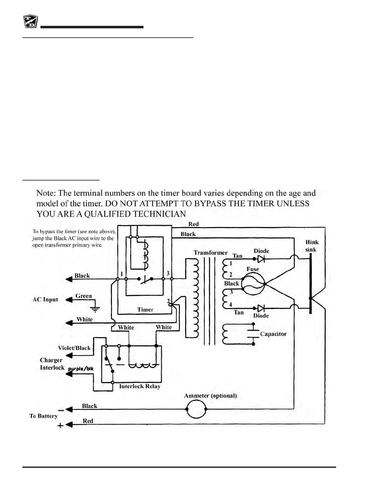
Internal Wire Diagram



 To Next Page