Page 12
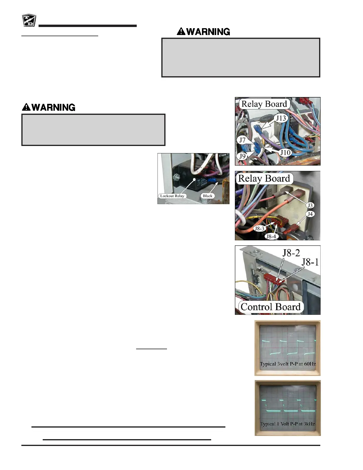
Relay Board Assembly
Note: To perform this procedure, the battery must have a
static voltage above 1.2 volts per cell. If not available,
a variable DC power supply can be used in place of
the battery. The power supply voltage should be set
to 12% higher then the rated charger DC voltage. If
using the power supply, the charger may report an
out of range voltage fault after about 10 seconds of
operation. Should this occur, turn the power supply OFF, then ON to continue
testing.
1. Remove the charger from the vehicle.
2. Disconnect the charger from the AC power source.
3. Remove the charger cover.
4. Disconnect the Black wire from the Lockout Relay
(reconnect when testing is completed).
5. Connect the charger to the AC power source and
check voltage at Relay Board terminals J9 and J10.
Should be the rated AC voltage of the charger. If not, then check the AC power source
and wiring to the Relay Board.
6. Check the AC voltage across Relay Board terminals J7 and J10. Should be the rated
AC voltage of the charger. If not, then replace the Relay Board.
7. Connect the charger to the battery. The relay should close (click). If the relay does not
close then skip the next test.
8. Check AC voltage across Relay Board terminals J7 and J13. Should be the rated AC
voltage of the charger. If not then replaced the Relay Board.
Continue ONLY if the Relay did not close.
9. Disconnect the charger from the AC power source and test DC voltage across Relay
Board terminals J3 (+) and J4 (-). This should be the same as battery volts. If this voltage
is low, then check wiring to the batteries.
10. Disconnect the charger from the battery.
11. Connect the charger to the AC power source.
12. Connect an oscilloscope to Control Board J8-2 terminal (use Relay Board J4 as ground).
Should see a 3 volt P-P square wave at 60 Hz. Note: This signal is only present with
the battery connected AND the charger is not ON.
• If out of specication, repeat the test at Relay Board J8-4. If still bad, replace the
Relay Board. If good, check the charger wiring.
Continue ONLY if test at J8-2 was Good.
13. Connect an oscilloscope to Control Board J8-1 terminal (use Relay Board J4 as ground).
Should see a 1 volt P-P square wave at 3 kHz.
• If out of specication then check all wiring to the Control board. If wiring OK,
replace the Control Board.
• If OK, repeat test at Relay Board J8-3. If bad, check charger wiring. If good, then
replace the Relay Board.
While connected to an AC outlet, the charger cabinet must
remain electrically grounded. Disconnect both of the
battery leads and unplug the charger from the AC source
before disconnecting any electrical component or wire.
Failure to do so may result in serious bodily injury.
High Voltage inside the charger. Do not touch any
internal components while the charger is plugged in.
Touching internal components may result in electric
shock causing severe bodily injury or death.
Don’t forget to reconnect the Lockout
Relay when testing is completed!