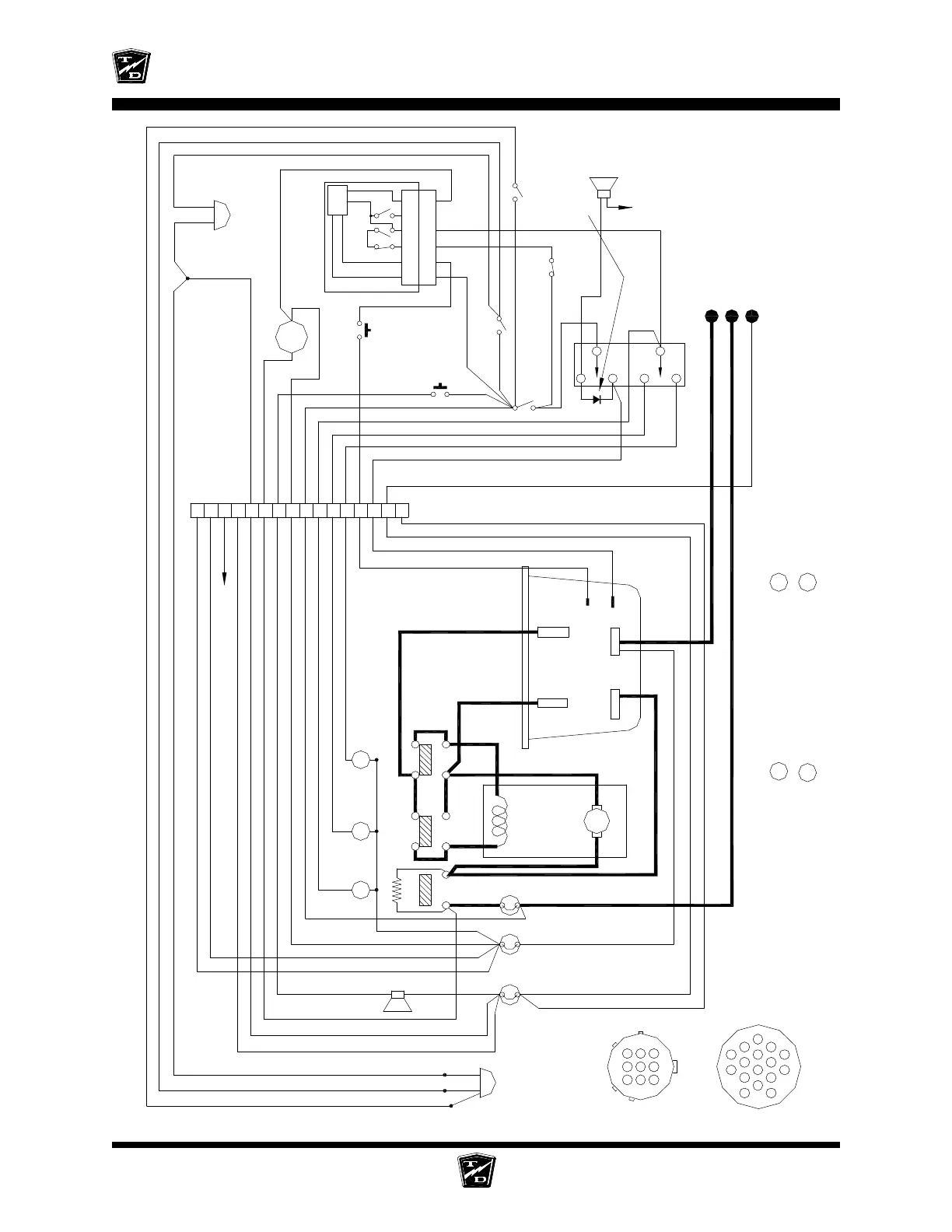
Wire Diagrams
Wire Diagrams Page 2
R1=250 OHMS 5W RESISTORCB = CIRCUIT BREAKER
Isolator solenoid or contactor coil
Brown
Red
BSI
Head Light
A
MOTOR
S1S2
A2
BL
FR I
A1
Blue
Green
Yellow
Green
KSI
B- B+
A2
M-
White
CB
135A
Black
Red
Red
Forward/Reverse Switch
Blue/Black
White/Black
Orange/Black
Green/Black
Horn
#2
R1
Violet/Black
PMC CONTROL
8
10
5
6
1
2
15
7
4
9
White
Black
Red
14
10A
CB
Light Switch
Blue
Violet/Black
Harness Connector
Red
Brown
White
Green/Black
White/Black
Blue/Black
Orange/Black
Blue
Orange
Orange
Brake Light Switch
LIGHT
TAIL/STOP
F
R
Typical PMC control system
Green/Black
Violet/Black
Violet/Black
Red
Brown
Blue/Black
White/Black
Green/Black
Red
Black
Blue
Red
White
Green
Orange/Black
Black
White White
Brown
Orange
White
Brown
Orange
White
Black
Red
Green
Red
Black
Black
White
Green
Violet/Black
Orange/Black
Black
Black
White
Red
Brown
Orange
Main Battery Positive
Main Battery Negative
12v negative tap
Green
Black
Red
White
CB
10A
R
FI
Reverse solenoid or contactor coil
Forward solenoid or contactor coil
BSI
Battery Status Indicator
Green/Black
Violet/Black
Violet/Black
Horn
Switch
Charger
Interlock Relay
Contacts
Key
Switch
The charger interlock is optional and may not be
installed on your vehicle. If equipped with the
charger interlock option the interlock relay will
be located in the main charger cabinet or in a
seperate module external of the charger.
14
16
6
10
2
15
7
3
11
1
View from wire side
13
4
7
6
9
View from pin side
Harness Connector
Accelerator Module Connector
16
White
White
13
Green
3
Connect to Forward or Reverse (+) for motion alarm
12
11
Black
Black
Black
White/Black
Black
ACCELERATOR
9
9
PCB
MS3MS1
MS2
5
5
6
6
4
4
2
2
7
7
Black
Black
Yellow/Black
To 12v negative tap
Optional Rev Alarm wiring
6-11v out
Seat or Foot
Interlock
Some components on diagram may not be installed on all vehicles