(1) Transformer
The transformer is located at the right side frame and converts input voltage to a voltage of the
level necessary for charging the battery.
There are three taps provided with a 10-volt difference from one to another. Make a selection
among them at the input side according to the input voltage level.
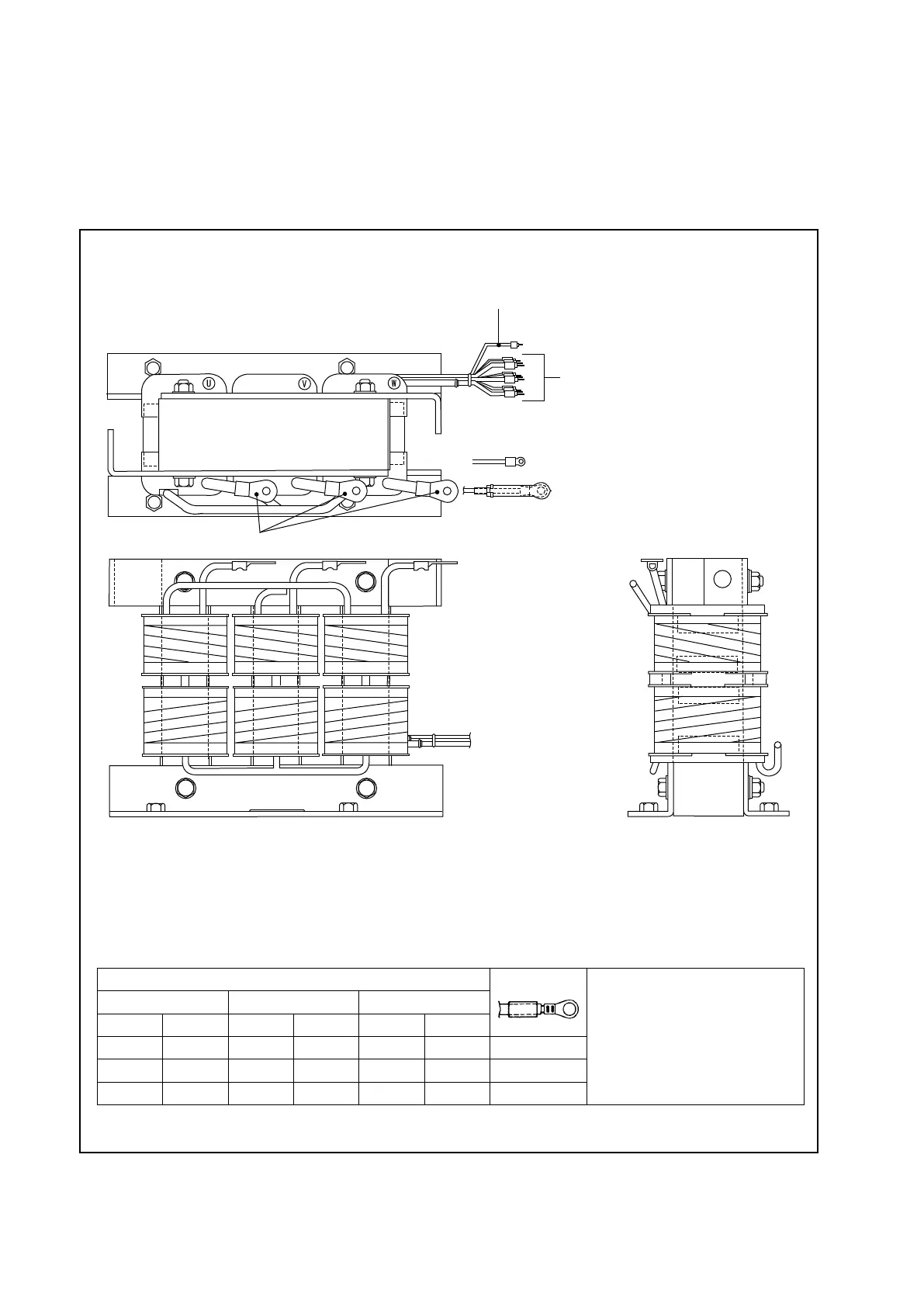
Fig. 1.6 Transformer
PRIMARY WIRE
GROUND WIRE (GREEN)
SECONDARY WIRE
■ Transformer tap changing
The supply voltage varies with the periods of time. Change therefore the taps from one to
another according to the average of supply voltages which to charger receives for the period of
time during which the battery is normally charged.
Supply Voltage (Average)
Symbol of Tap
Note 1: Change all the three
phases as a set.
Note 2: Give a terminal cap to
each of the taps which are
not used, and x them by
the wire binder.
205 V 390 V 440 V
50 Hz 60 Hz 50 Hz 60 Hz 50 Hz 60 Hz
180 - 190 190 - 200 340 - 360 360 - 380 390 - 410 410 - 430 L
190 - 200 200 - 210 360 - 380 380 - 400 410 - 430 430 - 450 M
200 - 210 210 - 220 380 - 400 400 - 420 430 - 450 450 - 470 H
1. BATTERY AND CHARGER (OPTION)