6.5 RESISTIVE PROGRAMMING OF OUTPUT VOLTAGE AND CURRENT LIMIT
For resistive programming, internal current sources, for output voltage and/or output current control,
supply 1mA current through external programming resistors co
23. The voltage across the programming resistors is used as a pr
gramming voltage for the power
10Kohm can be selected to program the output voltage and cu
rent limit from zero to full sca
A variable resistor can control the output over its entire range, or a combination of variable resistor and
series/parallel resistors can control the output over r
stricted portion of its range.
Perform the following procedure to set the power supply
to Resistive programming:
Set setup switch SW1 positions 1 and 2 to their UP position.
Set SW1 position 3 to select programming resistor range according to Table 6
Set SW1 positions 7 and 8 to their UP position to enable resistiv
Connect a short between J1
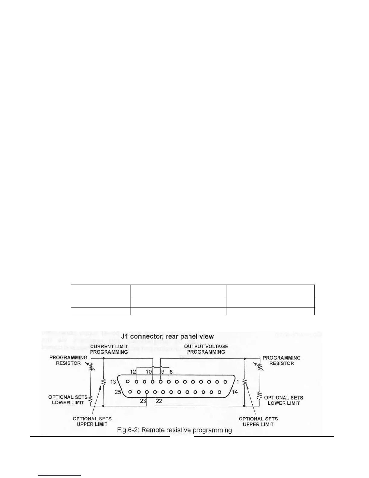
Connect the programming resistors to the mating plug of J1 as shown in Fig.6
Set the programming resistors to the desired resistance and turn the power supply ON. Adjust th
resistors to change the power supply output.
SW1 positions 4, 5, 6 and 9 are not required for remote programming. Their setting can be dete
mined according to the application requirements.
The control circuits allow the user to set the output vol
tage and current limit up to 5% over the
rated maximum value. The power supply will operate within the extended range, however it
is not recommended to operate the power supply over its voltage and current rating and perfor
maintain the temperature stability specification of the power supply, the resistors used for pr
gramming should be stable and low noise resistors, with temperature coeff
When resistive programming is used, front panel and compute
r control (via serial communication
port) of output voltage and current are disabled.
Current limit programming