EasyManua.ls Logo

TDK-Lambda GENESYS 10KW - Status, Error, and SRQ Registers Overview

TDK-Lambda GENESYS 10KW
74 pages
Print Icon
To Next Page IconTo Next Page
To Previous Page IconTo Previous Page
Loading...
83
-
530
-
000 Rev
G
62
7.10 STATUS, ERROR AND SRQ REGISTERS
7.10.1 General
This section describes the various status error and SRQ registers structure. The registers can be read
or set via the RS232/485 commands. When using the IEEE option, refer to the User’s Manual f
or
Gen
e
sys
TM
Power Supply IEEE Programming Interface.
Refer to Fig. 7
-
7 for the Status and Error Re
g
isters Diagram.
7.10.2
Conditional registers
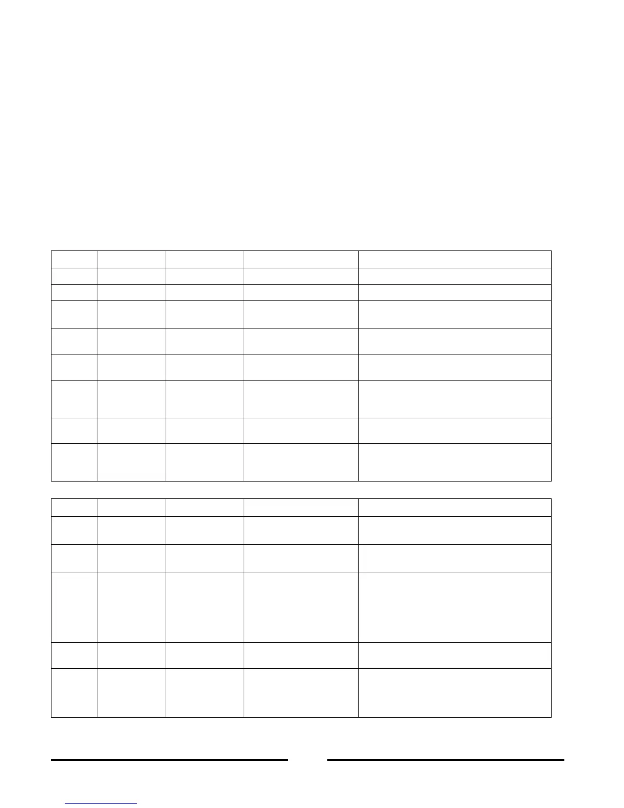
The fault Condition Register and the Status Condition Register are read only registers that the user
may read to see t
he condition of the supply. Refer to Table 7
-
8 for description of the Fault Condition
Register bits and Table 7
-
9 for the Status Co
n
dition register bits.
7.10.3
Conditional registers
Table 7
-
10: Fault Condition Register
BIT
Fault name
Fault symbol
Bit Set conditi
on
Bit Reset condition
0 (LSB)
Spare bit
SPARE
Fixed to zero
Fixed to zero
1
AC Fail
AC
AC fail has occurred.
The AC input returns to normal.
2
Over
temper
a
ture
OTP
OTP shutdown has
o
c
curred.
The power supply cools down.
3
Foldback
FOLD
Foldbac
k shutdown
has occurred
The supply output is turned On by front
panel button or OUT 1 command.
4
Over vol
t
age
OVP
OVP shutdown has
occurred.
The supply output is turned ON by front
panel button or OUT 1 command.
5
Shut Off
SO
Rear panel J1 “Shut
Off con
dition has o
c-
curred.
Rear panel J1 “Shut Off” condition r
e-
moved.
6
Output Off
OFF
Front panel OUT bu
t-
ton pressed to Off.
The supply output is turned On by front
panel button or OUT 1 command.
7(MSB)
Enable
ENA
Rear panel J1 Enable
terminal (J1
-
1&J1
-
14)
o
pened.
Rear panel J1 Enable terminals closed.
Table 7
-
11: Status Condition Register
BIT
Fault name
Fault symbol
Bit Set condition
Bit Reset condition
0 (LSB)
Constant
Voltage
CV
Output is On and the
supply in CV.
Output is ON and the supply is not in
CV.
1
Constant
Current
CC
Output is ON and the
supply in CC.
Output is ON and the supply is not in
CC.
2
No Fault
NFLT
The power supply is
operating normally or
fault reporting is not
enabled.
See “OUT n” co
m-
mand in Section 7.7.5.
One or more faults are ac
tive and fault
reporting is enabled (using “FENAxx”).
3
Fault active
FLT
One or more faults are
enabled and occur.
Fault Event Register cleared (FEVE?).
4
Auto
-
Restart
Enabled
AST
Supply is in Auto
-
Restart mode (from
Front Panel or serial
command).
Suppl
y is in Safe
-
Start mode (from
Front Panel or serial command).

Table of Contents

Related product manuals