6.6 REMOTE MONITORING OF OUTPUT VOLTAGE AND CURRENT
The J1 connector, located on the rear panel provides analog signals for monitoring the output voltage
and output current. Selection of the voltage range between 0
0V is made by setup switch
4. The monitoring signals represent 0 to 100% of the power supply output voltage and output cu
rent. The monitor outputs have 500 ohm series output resistance. Ensure that the sensing circuit has
r than 500 Kohm or accuracy will be reduced.
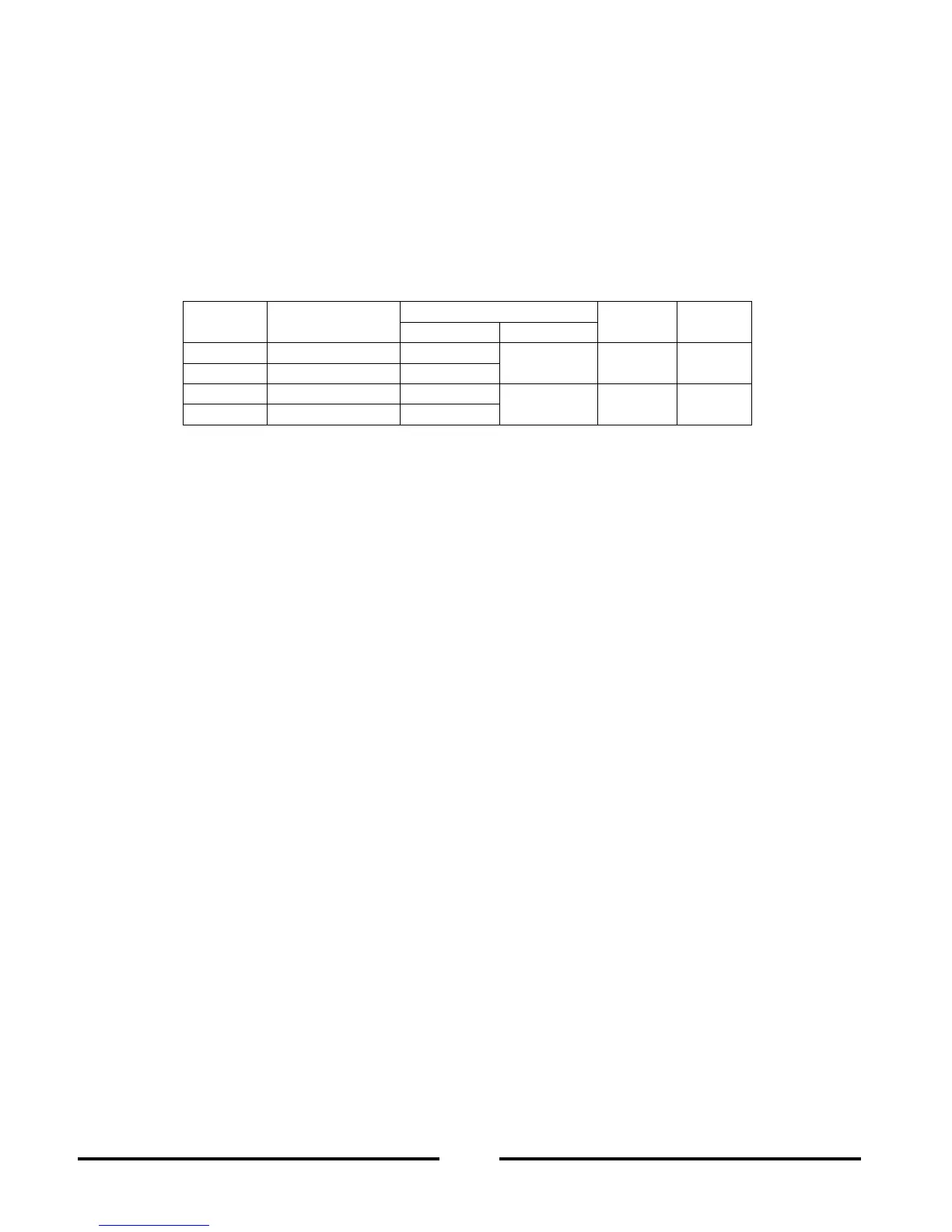
5 for required J1 connection, SW1
4 setting and monitoring voltage range.
5 Monitoring signals setting
1. Radiated emissions, FCC requir
FCC requirements for radiated emissions use shielded
analog control signals and connect shield to
chassis (As stud is provided near J1).
2. Front panel encoders operation:
In Remote analog mode the output voltage and current
can’t be set by the VOLTAGE and CURRENT encoders.
3. Front panel PREV button:
PREV button to display the output voltage and current
fined by the encoders or communication.
In Remote analog mode, power supply parameters can be
programmed and readback via the communication port e
cept output voltage and cu