EasyManua.ls Logo

TDK-Lambda GENESYS 10KW - Troubleshooting Guide Overview

TDK-Lambda GENESYS 10KW
74 pages
Print Icon
To Next Page IconTo Next Page
To Previous Page IconTo Previous Page
Loading...
83
-
530
-
000 Rev
G
68
8.3 ISOLATED PROGRAMMING & MONITORING CONNECTOR
Refer to Table 8
-
1 for detailed description of the rear panel Isolated P
rogramming & Monitoring
connector. To provide the lowest noise performance, it is recommended to use shielded
-
twisted pair
wiring.
Refer to Fig.8
-
1 for description of the connector.
Isolated programming plug P/N: MC1.5/8
-
ST
-
3.81, Phoenix.
Table
8
-
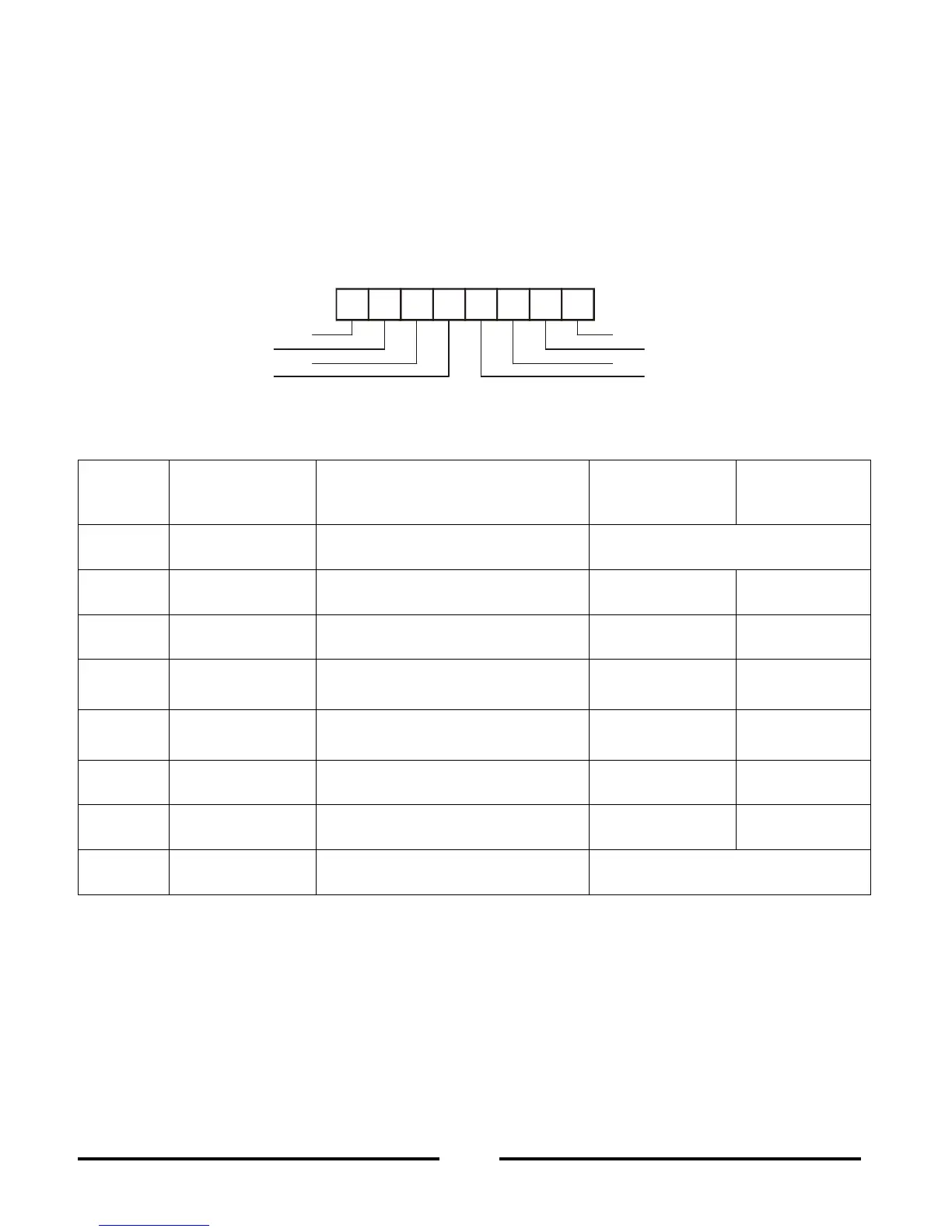
1: Detailed description of Isolated programming & Monitoring connector
Terminal
Signal name
Function
Range 0
-
5/0
-
10V
IS510 option
Range 4
-
20mA
IS420 option
1
SHLD
Shield, connected internally to
chassis of the supply.
Chassis ground
2
+VPROG_ISO
Outpu
t voltage programming i
n-
put
0
-
5/0
-
10V
4
-
20mA
3
+IPROG_ISO
Output current programming i
n-
put
0
-
5/0
-
10V
4
-
20mA
4
GND_ISO
Ground for programming signals.
Ground
Ground
5
GND_ISO
Ground for programming signals.
Ground
Ground
6
+VMON_ISO
Output voltage monit
oring output
0
-
5/0
-
10V
4
-
20mA
7
+IMON_ISO
Output current monitoring output
0
-
5/0
-
10V
4
-
20mA
8
SHLD
Shield, connected internally to
chassis of the supply.
Chassis ground
1
2
3
4
5
6
7
8
Shield
+VPROG_ISO
+IPROG_ISO
GND_ISO
Shield
+IMON_ISO
+VMON_ISO
GND_ISO
Fig.8-1: Isolated Programming & Monitoring connector

Table of Contents

Related product manuals