The following procedure ensures that the power supply is operati
onal and may be used as a basic i
coming inspection check. Refer to Fig. 4
2 for the location of the controls indicated in the
Ensure that the power supply is configured to the default se
Dip switch: All positions at Down (“Off”) position.
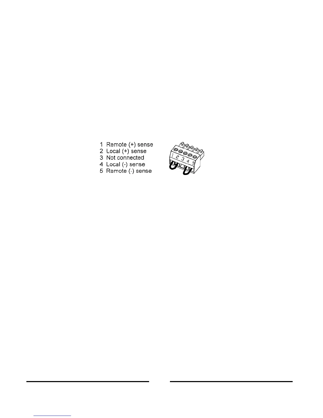
Sense connector: Configured to Local Sense as shown in Fig.3
4: sense connector default connection
For units equipped with IEEE option, ensure that the IEEE_En switch is
tion), if checkout is to be done in IEEE mode.
Connect the unit to an AC source as described in Section 3.7.
Connect a DVM with appropriate cables for the rated voltage to the output terminals.
rn the front panel ON/OFF switch to ON.
3.8.3 Constant Voltage Check
Turn on the output by pressing OUT pushbutton so the OUT LED illuminates.
Observe the power supply VOLT display and rotate the Voltage encoder. Ensure that the output
the VOLT encoder is rotated. The minimum control range is from zero to the
mum rated output for the power supply model.
Compare the DVM reading with the front panel VOLT display to verify the accuracy of the VOLT
display. Ensure that the front panel V
Turn off the front panel AC power switch.
3.8.4 Constant Current Check
Ensure that the front panel switch is at Off position and the DVM connected to the ou
Connect a DC shunt across the output terminals. En
sure that the shunt and the wires current ra
ings are higher than the power supply rating. Connect a DVM to the shunt.
Turn the front panel switch to On position,
Turn on the output by pressing OUT pushbutton so the OUT LED illuminates.
upply CURRENT display and rotate the CURRENT encoder. Ensure that the
output current varies while the CURRENT encoder is rotated. The minimum control range is from
zero to the maximum rated ou
put for the power supply model.
Compare the DVM reading with th
e front panel CURRENT display to verify the accuracy of the
CURRENT display. Ensure that the front panel CURRENT LED is on.
Turn off the front panel ON/OFF switch.