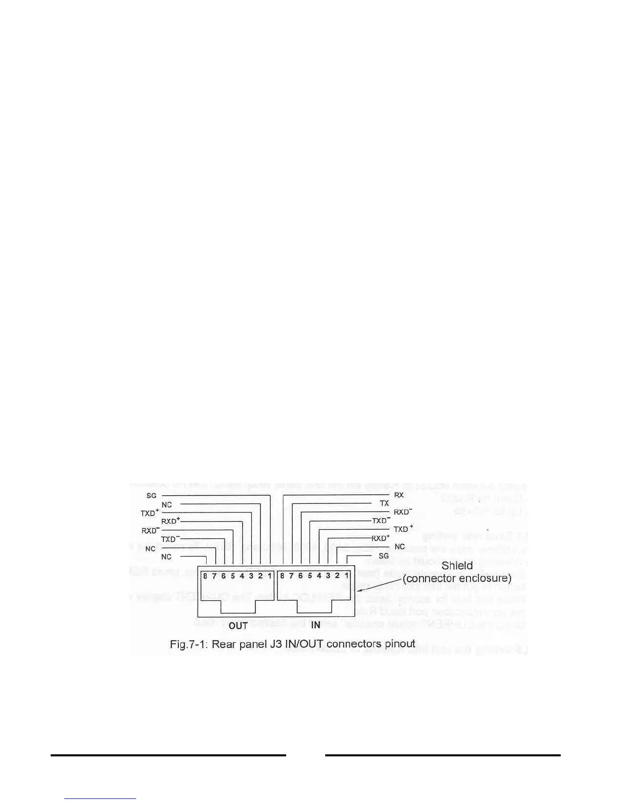
Tx and Rx are used for RS232 communication. Txd +/
communication. Refer to RS232 and RS485 cable description for conne
There are two Remote modes:
1. Remote: In this mode, return to local can be made by the front panel REM/LOC or via
mand RMT 0. Set the unit into Remote mode via s
2. Local Lockout: In this mode the unit can be returned to Remote mode via the serial port RMT 1
command or by turning off the AC power until the display turns off and then
recycling AC power. In lo
cal Lockout mode, the front panel REM/LOC button is
not active. Set the unit into Local Lockout mode via serial port RMT 2 command.
RS232/485 port in Local mode
When the power supply is in local mode, it can receive queries or commands. If a query is rece
the power supply will reply and remain in Local mode. If a command that affects the output is received,
the power supply will perform the command and change to Remote mode.
Serial commands may be sent to set the status registers and read them while t
he unit is in Local mode.
If the Enable registers are set (refer to Section 7.8) the power supply will transmit SRQ’s while in Local
Front panel in Remote mode
Front panel control in Remote mode is disabled except for:
PREV: use to preview the Voltag
e and Current limit setting.
OVP/UVL: use to preview the OVP/UVL setting.
LOC/REM: use to set the unit into Local mode.
In Local Lockout mode, only PREV and OVP/UVL are active.
7.3 REAR PANEL RS232/485 CONNECTOR
The RS232/485 interface is accessible thr
ough the rear panel RS232/485 IN and RS485 OUT conne
tors. The connectors are 8 contact RJ
45. The IN and OUT connectors are used to connect power su
plies in a RS232 or RS485 chain to a controller. Refer to Fig. 7