16
8303460000 Rev A IA672-04-01-Rev. I
5. LAN SETUP
5.1. View the IP and MAC Addresses
When the power supply is running with the LAN enabled, the IP and MAC addresses may
be viewed on the front panel by following these steps:
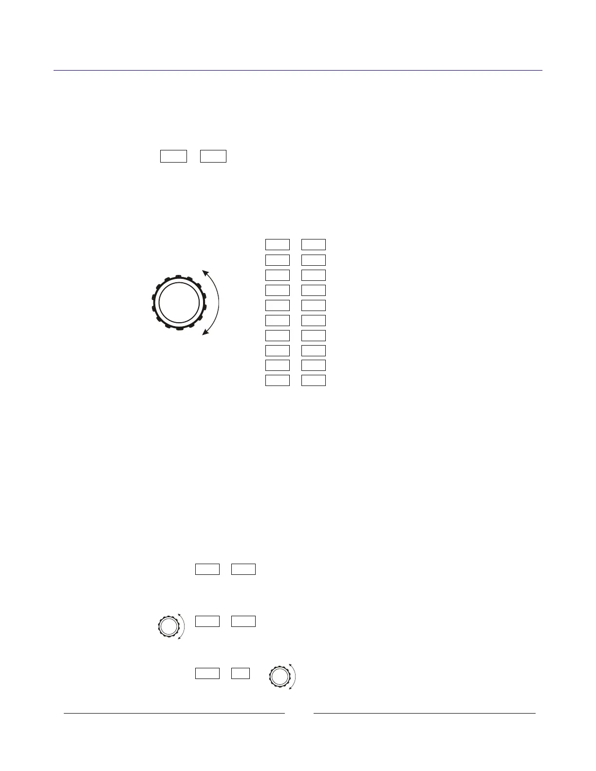
A. Press and hold the FOLD button for three seconds. The 7-segment displays will show
something such as:
IP-1 010
By turning the voltage encoder, the complete IP and MAC addresses may be seen.
All four numbers of the IP address may be changed through the web pages or from the
front panel (see next section). The MAC address cannot be changed.
The IP may not show on display if faults, such as Enable or Shut-Off, are in progress.
IP-1 10 In this example,
Rotate voltage knob IP-2 225
IP-3 26 – the IP address is:
IP-4 38 10.225.26.38
AC-1 00
AC-2 19 – the MAC address is:
AC-3 F9 00:19:F9:27:D3:B0
AC-4 27 (“AC” is short for “MAC”)
AC-5 d3
AC-6 b0
B. If the voltage knob is not changed for five seconds, the supply will revert to the normal
voltage and current displays. If this happens, press and hold the FOLD button again.
5.2. Change the IP Address
The LAN with revision after 2.0 allows you change all four numbers (octets) of the IP
address from the front panel. The IP address has four numbers (ex: “192.168.53.44”).
Each number may be set to any value from 1 to 254.
The power supply must be set to Local Mode to allow changing the IP address.
See section 3.2.1 to set local mode.
A. Press and hold the FOLD button for three seconds. The 7-segment displays will show
something such as:
IP-1 192 “192” is the 1
st
number in the address.
B. Rotate the voltage encoder until the display shows something such as:
IP-3 53 “53” is the 3
d
number in the address.
C. Rotate the current encoder to change the 3d number in the address:
IP-3 60 “60” is the new 3
d
number.